18s
Important safety instructions
- Read these instructions.
- Keep these instructions.
- Heed all warnings.
- Follow all instructions.
- Do not use this apparatus near water.
- Clean only with dry cloth.
- Do not block any ventilation openings. Install in accordance with the manufacturer’s instructions.
- Do not install near any heat sources such as radiators, heat registers, stoves, or other apparatus (including amplifiers) that produce heat.
- Do not defeat the safety purpose of the polarized or grounding-type plug. A polarized plug has two blades with one wider than the other. A grounding type plug has two blades and a third grounding prong. The wide blade or the third prong are provided for your safety. If the provided plug does not fit into your outlet, consult an electrician for replacement of the obsolete outlet.
- Protect the power cord from being walked on or pinched particularly at plugs, convenience receptacles, and the point where they exit from the apparatus.
- Only use attachments/accessories specified by the manufacturer.
 Use only with the cart, stand, tripod, bracket, or table specified by the manufacturer, or sold with the apparatus. When a cart is used use caution when moving the cart/apparatus combination to avoid injury from tip-over.
- Unplug this apparatus during lightning storms or when unused for long periods of time.
- Refer all servicing to qualified service personnel. Servicing is required when the apparatus has been damaged in any way, such as power supply cord or plug is damaged, liquid has been spilled or objects have fallen into the apparatus, the apparatus has been exposed to rain or moisture, does not operate normally, or has been dropped.
- WARNING: To reduce the risk of fire or electric shock, this apparatus should not be exposed to rain or moisture and objects filled with liquids, such as vases, should not be placed on this apparatus.
- To completely disconnect this equipment from the mains, disconnect the power supply cord plug from the receptacle.
- The mains plug of the power supply cord shall remain readily operable.

WARNING
Risk of electric shock. Do not open.
To reduce the risk of electric shock, do not remove the rear panel and do not expose the apparatus to rain or moisture. No user serviceable parts inside. Refer servicing to qualified personnel.
About this manual
Safety Icons
In this operating manual following icons and symbols are used.
General safety sign
The exclamation point within an equilateral triangle is intended to alert the user to the presence of important operating and maintenance (servicing) instructions in the literature accompanying the product.

Dangerous voltage
The lightning flash with arrowhead symbol within an equilateral triangle is intended to alert the user to the presence of uninsulated “dangerous voltage” within the product’s enclosure that may be of sufficient magnitude to constitute a risk of electric shock to persons.
Signal Words
NOTICE
Indicates in combination with a safety sign a hazardous situation which, if not avoided, will result in damage to equipment.
CAUTION
Indicates in combination with a safety sign a potentially hazardous situation which, if not avoided, could result in minor or moderate injury or damage to equipment.
WARNING
Indicates in combination with a safety sign a potentially hazardous situation which, if not avoided, could result in death or serious injury.
DANGER
Indicates in combination with a safety sign a hazardous situation which, if not avoided, will result in death or serious injury.
User Manual Structure
Following this introduction and a section describing the main features of the Sub 6, this manual is divided into three sections in which you can find all the information needed to install and use your Dynaudio Sub 6:
- Unpacking: Describes unpacking the subwoofer, environmental factors and the contents of the subwoofer carton.
- Installation: This section describes subwoofer positioning in general and where to locate your Sub 6 for optimum performance.
- Configuration and Use: This section describes the functions available through the Sub 6 user interface, how to configure the subwoofer optimally for your system. This section also covers the Sub 6 in use and how to fix any problems that might arise.
Introduction
Welcome to Dynaudio 18S active DSP subwoofer. The 18S is a very high performance product that rewards thoughtful setup and installation so we suggest that you take a little time to read this manual before you begin.
Getting to know the 18S
The Dynaudio 18S is a DSP controlled active subwoofer intended to augment the bass performance of full range monitors in near-field or mid-field monitoring installations.
The 18S features a closed box acoustic system and incorporates dual opposed 24 cm drivers to minimise mechanical vibration.
Connection facilities include balanced XLR and unbalanced stereo inputs with output sockets provided to enable the connection of active monitors, a power amplifier for passive monitors, or a second subwoofer.
The 18S incorporates low-pass filter presets configured to match a range of Dynaudio monitor models, three bands of parametric equalisation, an optional 80 Hz high-pass output filter and an adjustable low-pass filter that can be configured for use with monitors from alternative manufacturers.
18S configuration and control is accomplished through a rear panel mounted display combined with a rotary controller.
Unpacking

- Open the carton from the top and remove the subwoofer accessories. Do not remove the upper element of the internal packaging.
- Carefully rotate the carton on to its side and again to turn it upside-down.
- The carton can now be lifted away from the subwoofer. Remove the lower internal packaging now on top to reveal the underside of the subwoofer.
- Open the plastic bag and remove it from around the base of the subwoofer.
- Carefully rotate the subwoofer on to its side and again to turn it onto its feet. The internal packaging can now be removed followed by the plastic bag.
After unpacking, make sure the components are complete and check the subwoofer and all accessories for transport damage. Transport damage may be expected if the packaging is severely marked. Do not attempt to install the subwoofer if it is damaged. If the contents are incomplete or damaged, please contact your Dynaudio retailer or local distributor. Distributor addresses can be found at: www.dynaudio.com.
Packaging material
The packaging has been designed so that it may be reused if it was not damaged during initial transport. Keep the packaging and use it for all further transport.
Note
The 18S is heavy and is best unpacked close to its installed location by two people working together.
Disposal
Disposal of used electrical and electronic equipment (applicable in European countries with separate collection systems for this equipment).

This symbol on the product or its packaging indicates that the product may not be treated as household waste. Instead it must be handed over to the applicable collection point for the recycling of electrical and electronic equipment. By ensuring this product is disposed of correctly, you will help prevent potential negative consequences for the environment and human health. The recycling of materials helps to conserve natural resources. For more detailed information on recycling this product, please contact your local authority, community waste disposal of, or the shop where you purchased the product.
Carton contents
- 1 x Dynaudio 18S active DSP subwoofer
- 1 x Mains power cable
- 1 x Document pack
Installation
Positioning
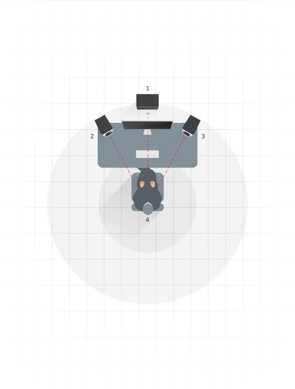
- 1 Subwoofer distance
- 2 Left monitor distance
- 3 Right monitor distance
- 4 Listening position
The position of subwoofers in studio rooms is generally less critical compared to full-range monitors. However, best results will most likely be obtained if your 18S is placed asymmetrically between the left and right monitors or in the vicinity of one of them. If this is not practical, a subwoofer position to the side of the left or right monitor, or against a side wall can also provide good results. Try to avoid symmetry in positioning a single subwoofer with respect to the studio room boundaries.
Placing a subwoofer close to or behind the listening position, even in multi-channel installations, generally results in inferior subjective performance, especially in terms of stereo imaging.
Note
Two subwoofers used in a single installation can improve performance by maintaining low frequency stereo separation and effectively averaging the effects of low frequency room resonances (room modes). Please see installation and configuration, below for multiple subwoofers. A simple place to start is by spacing multiple subwoofers equally across the front wall, as this can help stop width modes from forming.
Moving the subwoofer closer to walls and corners will generally increase the amount of bass. Although the extra bass can be compensated for by reducing the volume level of the subwoofer relative to the rest of the system, this can result in uneven bass response at the listening position. Experiment with the position of your 18S to find one which yields the best compromise between convenience, volume and even bass response.
When using a single subwoofer, placing the subwoofer at the listening position, moving around prospective placement positions and listening/measuring to the result can often give a good indication of the performance of the subwoofer. Using a broadband signal, such as pink noise available in the RTA section of the Dynaudio Sound Meter app (available free from the Apple app store), should highlight any impact of room modes in the frequency response.
Every studio room will have “room modes”, where at specific locations and frequencies, the bass may be under or overemphasised. This effect is likely to be stronger in square and rectangular shaped rooms. Experimenting with the position of the subwoofer is likely to reap benefits in terms of minimising room modes.
Using Distance compensation
The 18S incorporates signal processing that can compensate for the time delay and volume level differences between the subwoofer and monitors resulting from their relative positions with respect to the listening position. Once you have positioned your subwoofer, measure the distances as illustrated. The measured distances should then be specified at the appropriate locations in the subwoofer configuration menu. The configuration menu is described in the Configuration section of this manual.
The 18S signal processing is able to compensate for a maximum of 5.35 m difference between subwoofer and monitor distances to the listening position.
Mains and signal connections
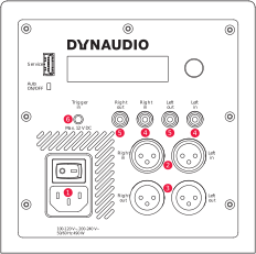
The 18S is fitted on its rear face with a connection and control panel carrying mains, signal and connection sockets. The panel is illustrated in Diagram 3 and its connection facilities are described in the following paragraphs.
1. Mains power socket
Connect the subwoofer to a mains power supply using the cable supplied. If multiple cables are supplied with your subwoofer, use the one appropriate for your territory.
Note
Do not switch on your subwoofer until all other connections have been made.
2. Balanced XLR input sockets (left and right)
If your monitoring hardware provides balanced outputs connect them to these sockets using high quality balanced XLR audio cables.
3. Balanced XLR output sockets (left and right)
The XLR output sockets are intended for the connection of active left and right monitors, a power amplifier driving passive monitors, or a second subwoofer.
Note
The 18S distance compensation signal processing can only function correctly if the monitors are driven via the subwoofer outputs.
Note
The 18S is equipped with an optional 80 Hz Linkwitz-Riley high pass filter on its XLR output sockets. Engaging the filter ensures that low frequency signals below 80 Hz are not passed to satellite speakers connected to the subwoofer outputs.
4. Unbalanced phono input sockets (left and right)
If your monitoring hardware provides unbalanced phono outputs connect them to these sockets using high quality phono audio cables.
Note
If your audio source provides only a mono subwoofer output it can be connected to any 18S input. In this case however the main monitors must be driven from the audio source and not via the 18S outputs.
5. Unbalanced phono output sockets (left and right)
The phono output sockets are intended for the connection of active left and right monitors, a power amplifier driving passive monitors, or a second subwoofer.
Note
The 18S distance compensation signal processing can only function correctly if the monitors are driven via the subwoofer outputs.
Note
The 18S is equipped with an optional 80 Hz Linkwitz-Riley high pass filter on its phono output sockets. Engaging the filter ensures that low frequency signals below 80 Hz are not passed to satellite speakers connected to the subwoofer outputs.
6. Trigger input
The 12 VDC trigger input enables wired remote control of subwoofer standby and operational modes in automated systems (5-12 VDC = ON). Your Dynaudio retailer or installer will be able to provide more information on the use of the 18S in automation systems.
Note
The USB socket present on the 18S connection panel is intended for fault diagnosis and firmware update only. It cannot be used for audio connection or playback. Contact your Dynaudio retailer or Dynaudio directly for more information of firmware updates.
18S Connections Schemes
Three common connection schemes are illustrated here.
Connection Scheme 1
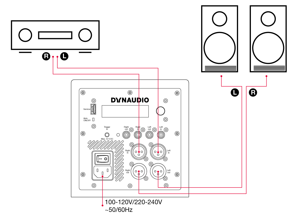
- Balanced (XLR) connection from preamplifier/processor to subwoofer inputs.
- Balanced connection from subwoofer outputs to active main speakers.
- The subwoofer should be distance-aligned as described above.
Connection Scheme 2
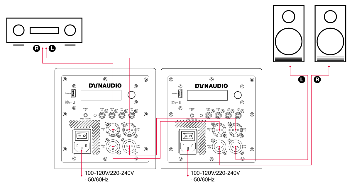
- Balanced (XLR) connection from preamplifier/processor to first subwoofer inputs.
- The first subwoofer’s input sensitivity should be set to match the preamplifier/processor outputs.
- In order to time-align the subwoofers the latency of the second subwoofer needs to be accounted for. This is done by adding 0.86 m to the left and right distance setting in the first subwoofer. The distance used in the setting should be the distance from the listening position to the second subwoofer plus 0.86 m. The subwoofer distance should be set as the distance to the first subwoofer. See Calculation.
- Balanced connection from first subwoofer outputs to second subwoofer inputs.
- The second subwoofer’s input sensitivity should be set to 0 dB.
- Balanced connection from second subwoofer’s outputs to the active main speaker’s inputs.
- The second subwoofer should be distance-aligned as described above.
- The subwoofers should be level-aligned using their volume setting.
Calculation
| First Subwoofer | Second Subwoofer | ||
|---|---|---|---|
| Left Speaker Distance | distance to second subwoofer + 86 cm | Left Speaker Distance | distance to left speaker |
| Right Speaker Distance | distance to second subwoofer + 86 cm | Right Speaker Distance | distance to right speaker |
| SUB Distance | distance to first subwoofer | SUB Distance | distance to second subwoofer |
Connection Scheme 3
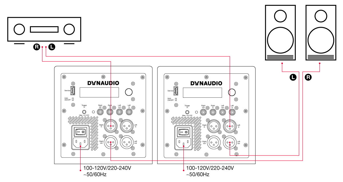
- Stereo subwoofers.
- Left balanced (XLR) connection from preamplifier/processor to left subwoofer, left input.
- Balanced connection from left subwoofer output to the left active main speaker.
- The left and right speaker distances in the left subwoofer should be set the as the left speaker distance described above. The Sub Distance should be set as the left subwoofer distance.
- Right balanced (XLR) connection from preamplifier/processor to right subwoofer, right input.
- Balanced connection from right subwoofer output to the right active main speaker.
- The right and left speaker distances in the right subwoofer should be set the as the right speaker distance described above. The Sub Distance should be set as the right subwoofer distance.
Control and configuration
Subwoofer controller
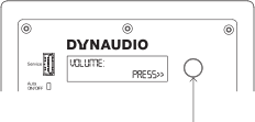
Rotary controller:
- Rotate to select.
- Press to confirm.
- Hold to exit menu.
Configuration and Use
With the 18S subwoofer positioned in the listening room and connected to signal cables and mains power it can be switched on via the mains switch above the mains input socket on the rear panel.
The 18S must be configured appropriately for the audio system and main speakers with which it is to be used. This is achieved via the rotary controller, display and menu based interface on the rear panel. Turn the rotary controller to select configuration parameters and press the control to select options and save any changes.
General Tips
Check it out
Try different subwoofer positions and settings, before you finally choose a setup.
Note down settings
When looking for the best subwoofer position in the room, note down the ideal setting you found for a position. When moving the subwoofer between two positions you will be able to set the subwoofer to the same configuration as found before.
Vary the listening music
When experimenting to find the optimal settings, use a couple of music tracks with repetitive bass across a large spectrum. The tracks should be sufficiently different from each other and each should cover a wide bass-range.
Musical instruments, such as a double-bass, bass guitar, church organ, etc. covering a wide spectrum in the bass region and above, are very suitable as these depend on accurately balanced subwoofers and main speakers.
Verify changes
Although in general it is best to make adjustments in the sequence outlined below, note that changing one setting may influence another. For example, finding the right setting for phase may result in having to decrease gain, even if this was set correctly before.
It is recommended that you double-check the previous settings before moving on to the next one. Obtaining the best integration of the subwoofers generally involves a considerable amount of repeated fine-tuning.
Note
If multiple subwoofers are employed, they should be configured as described in Installation.
18S Configuration Menus
Auto, ON/OFF
The Auto, ON/OFF switch enables auto standby (Auto) or forces the subwoofer to be permanently on (ON/OFF).
In Auto mode, the subwoofer can be “woken up” by
- an audio input signal,
- rotary knob push,
- a trigger input if Trigger is enabled in the menu.
Menu structure:
-
- PEQ Bypass
- PEQ 1
- Frequency
- Gain
- Q
- PEQ 2
- Frequency
- Gain
- Q
- PEQ 3
- Frequency
- Gain
- Q
-
- Disable
- ON/OFF
- Mute sub with High pass
- Mute sub without High pass
For more information, see the following sections.
Volume
Set to match the volume of your main speakers so that bass at your main listening position is neither too prominent or too quiet. Setting the subwoofer volume is important in terms of both overall system balance and the demands of different types of programme material.
Input sensitivity
Adjusts the input sensitivity to match the output level of your pre-amplifier or audio-visual processor.
Setting Input Sensitivity
The wide variety of possible source equipment types that can be connected to an active subwoofer means that it is important to set the input sensitivity appropriately. Doing so will help ensure that the subwoofer’s volume adjustment range is adequate and that its input and DSP electronics are driven properly.
If the source equipment has a published specification for output level, begin by setting the 18S input sensitivity to match the specification as shown in this table:
| Source Output Level | 18S Setting |
|---|---|
| <1.0 V | +6 dB |
| <2.0 V | 0 dB |
| <4.0 V | -6 dB |
| <10 V | -14 dB |
The -14 dB sensitivity setting should generally be used when the 18S is used for the LFE channel in a home theatre system.
If the source equipment has no published output level specification, begin by setting the Input Sensitivity to -6 dB. If then when in use the 18S volume setting is required to be towards either its maximum or minimum values, adjust the Input Sensitivity appropriately such that the volume setting is towards the middle of its range.
Preset
The 18S incorporates low pass filter presets for a range of Dynaudio speaker models.
If your 18S is to be used in a system with one of the Dynaudio models listed, select it to automatically configure the 18S low pass filter appropriately.
If your Dynaudio speaker model is not listed among the 18S presets, or if your 18S is to be used with speakers from an alternative manufacturer, select a low pass filter frequency closest to the speaker’s specified -6 dB low frequency cut-off.
If your subwoofer is to be used for the LFE channel in a home theatre system select the filter Bypass option.
Note
Matching the filter frequency of the subwoofer to the bass cut-off frequency of the main speakers will have an important impact on the overall system sound quality. In general, larger main speakers will have more extended bass so will require a lower subwoofer filter frequency. Conversely, smaller main speakers are likely to require a higher subwoofer filter frequency. If the subwoofer filter frequency is not set optimally, the overall frequency response of the system may display an audible peak or dip around the crossover frequency. The diagram opposite illustrates the three frequency response characteristics that might result from optimum and non-optimum subwoofer filter settings.
Subwoofer filter frequency set too low
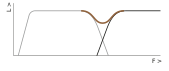
- L: Level
- F: Frequency
- Dark grey line: Main speakers
- Light grey line: Subwoofer
- Brown line: System response
A dip in the system response will occur if the filter frequency of the subwoofer is set too low – perhaps with small main speakers that do not have extended bass response. The result will be missing musical information and a thin overall sound.
Subwoofer filter frequency set too high

- L: Level
- F: Frequency
- Dark grey line: Main speakers
- Light grey line: Subwoofer
- Brown line: System response
A peak in the response will occur if the filter frequency of the subwoofer is set too high – perhaps with large main speakers that have an extended bass response. The result will be an excess of mid-bass energy that will sound unnatural and bloated.
Subwoofer filter frequency set optimally
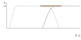
- L: Level
- F: Frequency
- Dark grey line: Main speakers
- Light grey line: Subwoofer
- Brown line: System response
The subwoofer and main speakers are well matched. The system frequency response is smooth without a peak or dip. A well balanced sound will result.
Phase
With the phase settings you can adjust the phase relationship between the subwoofer and main speakers. If either subwoofer or main speaker are slightly out of phase in relation to the other, it can result in decreased bass output in the frequency response area where they overlap each other.
Parametric EQ (PEQ)
Provides three bands of low frequency parametric equalisation. Each band offers frequency, gain and Q parameters. The equalisation is set “flat” by default.
Using Parametric Equalisation
The digital signal processing power incorporated in 18S enables three bands of parametric equalisation to be applied to the input signal. Parametric equalisation can be viewed as finely targeted tone control that is able to correct specific frequency response anomalies caused by room acoustics.
It should only be used after the subwoofer position has been finalised.
Each band of parametric equalisation offers three control parameters: frequency, level and Q. “Frequency” defines the centre frequency around which the equalisation band operates, “level” defines the degree of boost or cut, and “Q” defines the width of the equalisation band (a higher Q means a narrower band). These control parameters are illustrated in the diagram opposite.
The 18S Parametric EQ is intended to be used in combination with professional room acoustic analysis to identify response anomalies, however the Dynaudio Sound Meter app (available free from the Apple app store) incorporates a real time frequency analyser that can be used to help identify anomaly frequencies and so guide parametric equalisation set up.
Sit in your main listening position, launch the Sound Meter app and select the RTA option while playing a “pink noise” signal through the subwoofer (pink noise can be found on many music streaming services). Prominent peaks in the response curve displayed by the app will most likely correspond with any audible frequency response anomalies. Equalisation bands can then be set at the anomaly frequencies and the level and Q parameters adjusted to flatten the response curve.
Further guidance on using subwoofer parametric equalisation can be found on the 18S product page at dynaudio.com.
Note
The diagram shows one band of parametric equalisation set with a relatively high Q (approx 5) and approximately 6 dB of attenuation.
The Parametric EQ of the 18S is a powerful tool and it should be used carefully. In the vast majority of circumstances equalisation should be used to attenuate room anomalies rather than not to boost subwoofer bass. If more bass is required always try repositioning the subwoofer first.
Parametric EQ parameters
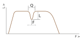
- L: Level
- F: Frequency
- Q: Quality factor
HP Filter
Engages or disengages a 4th order, 80Hz Linkwitz-Riley high-pass filter on the Left/Right outputs. Engaging the high-pass filter ensures that low frequency signals below 80Hz are not passed to satellite speakers connected to the subwoofer outputs.
Auto standby
Select to specify the delay time before the subwoofer will switch to Standby mode when unused. The auto standby feature can also be switched off using the Auto On/Off switch on the backplate.
Trigger (5 - 12 VDC = on)
Select one of four options:
- Disable: Trigger input is ignored.
- ON/OFF: Trigger input is required to turn the 18S on.
- Mute sub with High pass: Trigger input mutes the 18S with main speakers high passed.
- Mute sub without High pass: Trigger input mute the 18s with out high pass filtering the main speakers.
Left main speaker distance
Select to specify the distance in centimetres of the left main speaker from the listening position.
Right main speaker distance
Select to specify the distance in centimetres of the right main speaker from the listening position.
Subwoofer distance
Select to specify the distance in centimetres of the subwoofer from the listening position.
Factory Reset
Select to return your 18S to its default settings.
Software version
Displays the installed firmware version.
In use
Once installed and configured, your 18S should require little attention other than perhaps occasional volume control adjustment to suit different types of programme material.
Cleaning your subwoofer
Brush the cabinet surfaces with a clean lint-free cloth. Do not use a vacuum cleaner. If you wish to use a cleaning agent, apply it to the cleaning cloth and not directly to the subwoofer. Test a small area first, as some cleaning products may damage some of the surfaces.
Support
Should you require help or advice there are a variety of support options for Dynaudio products. These can be found at dynaudio.com.
Updating the Firmware
To update the firmware of your Dynaudio subwoofer, proceed as follows. Make a note of the settings in the subwoofer as a Factory Reset may be required after update.
Requirements
- Empty USB stick formatted to FAT32. (a maximum capacity of 8GB is preferable)
- The latest firmware file downloaded from dynaudio.com/support/firmware
Firmware Update Procedure
- Unzip the downloaded Zip file.
- Copy the “DYNAUDIO.bin” firmware file into the root directory of the USB stick.
- Switch OFF the subwoofer with the rear-panel switch.
- Insert the USB stick into the USB port at the rear panel labeled “Service”.
- Switch ON the subwoofer with the rear-panel switch.
- Your subwoofer will automatically download the firmware from the USB stick.
- After this, let the subwoofer install the full update, which should take 1- 3 minutes. DO NOT TURN THE DEVICE OFF DURING THIS PROCEDURE.
- During this update the LED will change from red to blue, and the display will show various messages about the update progress.
- After installation is complete, the LED will turn green and the display will return the message: Update result: Success!
- Your firmware update procedure is now finished. Switch OFF the subwoofer and remove the USB stick.
- Switch the subwoofer ON.
- Check the firmware version in the menu info screen.