9S
Important safety instructions
- Read these instructions.
- Keep these instructions.
- Heed all warnings.
- Follow all instructions.
- Do not use this apparatus near water.
- Clean only with dry cloth.
- Do not block any ventilation openings. Install in accordance with the manufacturer’s instructions.
- Do not install near any heat sources such as radiators, heat registers, stoves, or other apparatus (including amplifiers) that produce heat.
- Do not defeat the safety purpose of the polarized or grounding-type plug. A polarized plug has two blades with one wider than the other. A grounding type plug has two blades and a third grounding prong. The wide blade or the third prong are provided for your safety. If the provided plug does not fit into your outlet, consult an electrician for replacement of the obsolete outlet.
- Protect the power cord from being walked on or pinched particularly at plugs, convenience receptacles, and the point where they exit from the apparatus.
- Only use attachments/accessories specified by the manufacturer.
 Use only with the cart, stand, tripod, bracket, or table specified by the manufacturer, or sold with the apparatus. When a cart is used use caution when moving the cart/apparatus combination to avoid injury from tip-over.
- Unplug this apparatus during lightning storms or when unused for long periods of time.
- Refer all servicing to qualified service personnel. Servicing is required when the apparatus has been damaged in any way, such as power supply cord or plug is damaged, liquid has been spilled or objects have fallen into the apparatus, the apparatus has been exposed to rain or moisture, does not operate normally, or has been dropped.
- WARNING: To reduce the risk of fire or electric shock, this apparatus should not be exposed to rain or moisture and objects filled with liquids, such as vases, should not be placed on this apparatus.
- To completely disconnect this equipment from the mains, disconnect the power supply cord plug from the receptacle.
- The mains plug of the power supply cord shall remain readily operable.

WARNING
Risk of electric shock. Do not open.
To reduce the risk of electric shock, do not remove the rear panel and do not expose the apparatus to rain or moisture. No user serviceable parts inside. Refer servicing to qualified personnel.
About this manual
Signal words

The lightning flash with an arrowhead symbol within an equilateral triangle, is intended to alert the user to the presence of uninsulated “dangerous voltage” within the product’s enclosure that may be of sufficient magnitude to constitute a risk of electric shock to persons.
The exclamation point within an equilateral triangle is intended to alert the user to the presence of important operating and maintenance (servicing) instructions in the literature accompanying the product.
Caution
Indicates a potentially hazardous situation which, if not avoided, could result in damage to equipment.
CAUTION
Indicates in combination with a safety sign a potentially hazardous situation which, if not avoided, could result in minor or moderate injury or damage to equipment.
WARNING
Indicates in combination with a safety sign a potentially hazardous situation which, if not avoided, could result in death or serious injury.
DANGER
Indicates in combination with a safety sign a hazardous situation which, if not avoided, will result in death or serious injury.
This manual is divided into three main chapters.
- Before you start: Learn how to unpack and connect the subwoofer.
The controls and connections on the back panel are also described here. - Operation: In this chapter you will learn how to operate the subwoofer and how to position it properly for optimum performance.
- Optimising settings / Troubleshooting: Detailed explanations on how to optimise settings to achieve maximum sound quality.
Before you start
Unpacking the subwoofer

- Unpack the subwoofer on a clean, flat and soft surface; floor carpeting is suitable.
- The packaging should be opened from the top (1). Remove all accessories packed with the subwoofer (such as the AC power cord). Do not remove the top part of the protective material.
- With the protective material still in place but with accessories removed, carefully tilt the packaging on its side (1) and tilt again to turn it upside-down (2). Ensure that no part of the top-cover is obstructing the opening at the top.
- The outer packaging can now be lifted away from the subwoofer itself (3). Remove the protective material that now is on top.
- Open the bag and remove it from around the base of the subwoofer.
- Again, carefully tilt the subwoofer on its side and again to turn it onto its feet. Note that the top part of the protective material will now come off easily so ensure that the subwoofer doesn’t drop or slide away in the process.
Check that the contents are complete:
- Subwoofer: The factory-set power requirements (refer to label on rear of subwoofer) should correspond to the territory in which the subwoofer was purchased. Refer also to the Important safety instructions.
- AC mains lead. The supplied lead should be suitable for the territory in which the subwoofer was purchased.
- This owner’s manual.
Controls and connections
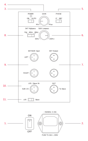
1. POWER ON (Main)
Mains power switch (to switch the subwoofer manually on and off). The LED indicates the operational mode:
- red: the subwoofer switched on and in mute (Standby) mode
- green: the subwoofer is active
2. AC IN
Mains power input.
3. Power (Mode)
On: subwoofer is permanently on
Auto: subwoofer switches on when an input signal is detected
4. Gain
Subwoofer volume level.
5. Phase
Phase setting: phase can be set to 0° or 180°.
6. Low-pass
Subwoofer low-pass frequency: continuously variable from 50 to 150Hz.
7. SAT/SUB (output)
Output for connection of satellite speakers. This signal is processed according to the high-pass filter setting.
8. High-pass
Applies a high-pass filter to the signal routed to the T/SUB output:
Flat: signal is not processed
60: filter frequency at 60Hz
80: filter frequency at 80Hz
9. SAT/SUB (input)
Input for full bandwidth signal. The signal will be processed according to the high-pass filter setting and routed to the SAT output.
10. LFE
LFE
LFE/Slave: input for LFE signal
Slave: output to (second) slave subwoofer if present
11. Mode
Subwoofer operation mode LFE or Slave:
LFE: select for normal or master use
Slave: select for slave use
Terminal pinout (sockets 9, 10 and 11)
- 1 = 0
- 2 = +
- 3 = –
Damage due to improper connections!
CAUTION
Improper connections may damage the device.
Set the mains power switch to OFF before connecting the 9S.
Only switch on the subwoofer (mains power switch to ON) after all connections and configuration steps have been completed.
Subwoofer inputs
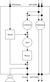
The 9S provides two different signal inputs:
LFE/Slave
This input allows the LFE (Low Frequency Effect) channel to be connected. The signal is:
- reproduced by the subwoofer
- routed to the Slave output for a second subwoofer to be connected.
The low-pass control has no impact on this input.
SAT/SUB
This input allows the connection of a full bandwidth signal. The signal is:
- reproduced by the subwoofer
- routed to the SAT output terminals. Low frequencies are filtered according to the high-pass setting
- routed to the Slave output for a second subwoofer to be connected.
- High frequencies are filtered according to the low-pass setting.
Connecting a single subwoofer
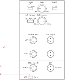
Connecting as LFE channel (1.)
Connect to subwoofer LFE/Slave input.
Connecting as subwoofer for satellites (2.)
- Connect the full bandwidth signal to the SAT/SUB input. The subwoofer reproduces the sum of right and left signals.
- Set the Mode switch to LFE.
Note:
- Both connection types can be used simultaneously. The signals will be combined in the 9S and routed accordingly. This enables the 9S to reproduce both the LFE channel information as well as the bass range of the connected satellite system.
- Use Slave mode if external bass management is to be employed.
Multiple subwoofer connections
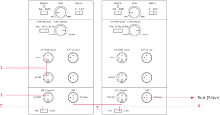
The 9S can be used stand-alone or together with multiple subwoofer units. Using multiple units may be helpful if the listening room is large or has difficult acoustic conditions. When using two or more subwoofers, the first one (designated “Master”) controls the following subs (designated “Slave”) via a subwoofer cable.
To connect multiple subwoofers:
- Connect the first subwoofer as described previously.
- Set the Mode switch of first subwoofer to LFE.
- From the Slave output of the first subwoofer connect a XLR cable to the LFE/Slave input of the following subwoofer. This one now becomes the slave.
- Set the Mode switch of the second subwoofer to Slave.
Further subwoofers can be connected in the same way. Set the Mode switch of all following subwoofers to Slave.
Note:
When using multiple subwoofers in a Master-Slave setup, it is recommended that the subwoofers are all the same model.
If you wish to use multiple subwoofers with full individual control, set the Input switch for all to the LFE position. From the source subwoofer output, use a Y-connector.
Connecting loudspeakers
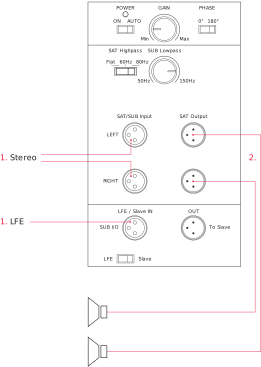
If the signal source includes a bass management function, the subwoofer LFE input alone can be used in LFE or SLAVE mode, depending on the management system capabilities. Avoid double LFE filtering if possible.
To connect loudspeakers
- Connect the subwoofer (see “Connecting a single subwoofer”).
- From the subwoofer SAT output connect a XLR cable to the inputs of the power amplifier you use for your speakers.
Note
The signals connected to the inputs are provided at the Slave output for connecting another subwoofer. See the later section on multiple subwoofers to learn more.
Operation
Switching on the subwoofer
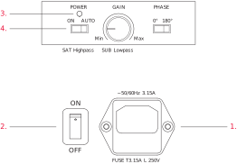
Once you have ensured that all necessary connections have been made, the subwoofer and the connected components can be switched on.
- Connect the subwoofer to the mains power.
- Switch the subwoofer on with the main POWER switch on the rear panel.
- The status LED on the rear of the subwoofer will indicate red.
- Select a power mode with the Power switch on the rear panel.
Power modes
On: the subwoofer is switched on permanently
Auto: when a music signal is detected, the internal amplifier is activated automatically. The status LED on the back of the subwoofer will indicate green. As long as a music signal is present on the subwoofer input, it will remain switched on.
After 15 to 20 minutes of not sensing any input music signal, the subwoofer will switch itself to Standby mode automatically. The status LED on the back of the subwoofer will indicate red.
Note
To switch the subwoofer completely off, set the main POWER switch to the OFF position.
Adjusting the volume (Gain)
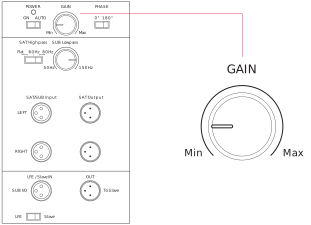
CAUTION
High Sound Levels!
High sound levels can cause hearing damage. Do not listen to high sound levels for extended periods of time.
The correct volume setting is an important aspect of achieving a well balanced speaker combination.
To adjust the gain
Adjust the Gain control until the appropriate setting is reached.
Note
You cannot adjust the volume when the subwoofer is in slave mode. In this case the volume is controlled by the setting of the master subwoofer.
Selecting the subwoofer filter frequency (low-pass)
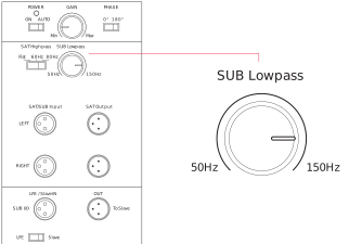
The Low-pass control allows the frequency range of the subwoofer to be defined. Above the selected frequency the sound level decreases rapidly. The correct setting of this filter frequency is important for a well balanced combination of subwoofer and speakers.
To select the filter frequency
Set the Low-pass control to the desired frequency between 50 and 150Hz.
Note
The Low-pass only works on SAT/SUB input.
The subwoofer filter frequency may already be set by the source component bass management. Refer to the operating manual of the source component. In general use only one bass management system.
You should also heed the instructions given in the operating manual of your loudspeakers.
Setting the phase (Phase)
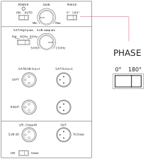
With the phase settings you can adjust the phase relationship between the subwoofer and main speakers. If either subwoofer or main speaker are slightly out of phase in relation to the other, it can result in decreased bass output in the frequency response area where they overlap each other.
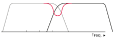
- Red: Combined frequency response
- Grey: Subwoofer
- Black: Main speakers
The phase relationship between subwoofer and satellite speakers is dependent on their relative distance to the listening position and on the working principles of the satellite speakers. The figure above shows a case in which the phase of the subwoofer and satellite speakers is incorrect in the critical overlap area, thus reducing acoustic output in the listening room in that region.
To find the correct phase setting
- Play a bass-rich track which also covers the overlap area.
- Toggle the Phase switch between 0° and 180°. Choose the setting with which you experience the most consistent bass.
Note
The phase cannot be set if the subwoofer is in slave mode. In this case the phase is controlled by the setting of the master subwoofer.
Setting the satellite cut-off frequency (high-pass)
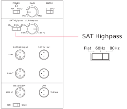
Depending on the bass capabilities of the speakers, the frequency range of subwoofer and speakers can overlap between 50Hz and 150Hz. A bump or a gap in the frequency response will result in lower sound quality. In addition, small speakers and low powered amplifiers are particularly stressed by low frequency signals, which again has a negative effect on the sound quality. It is useful therefore to limit the bass range of the connected speakers (called “satellites” in this case) through a high-pass filter. The 9S provides two high-pass filter settings to achieve this:
- Flat = no filter
- 60Hz = frequencies below 60Hz are filtered.
- 80Hz = frequencies below 80Hz are filtered.
To set the filter frequency
Switch the High-pass control to the required position.
Troubleshooting
There may be various reasons why a subwoofer doesn’t function properly in a system without it being faulty. The checklist below will help solve any problems you may encounter. Before consulting your Dynaudio Professional dealer, check this list first.
Check this first:
- Check if all signal cables are connected properly.
- Check settings in the bass management setup of the connected source.
- Gradually increase the source subwoofer volume level.
- Gradually increase the subwoofer Gain control level.
Problem
The subwoofer switches itself off while music is being played.
Cause
There is little low-frequency content in the signal. This can happen if the music or movie itself does not contain very low frequencies (e.g. long dialogues).
Solution
The subwoofer will switch on automatically as soon as low frequent music signals are detected. Switch subwoofer off and on again by means of the main POWER switch.
Problem
The subwoofer will not switch on at all.
Cause
- Mains cable has become disconnected (LED is not lit)
- Mains switch on the back is switched to OFF (LED is not lit)
Solution
Make sure to switch off the system before making any changes!
- Reconnect mains cable.
- Switch mains back on.
- Check if all signal cables are connected properly.
Problem
The subwoofer will not switch on automatically.
Cause
No signal is present on either of the subwoofer inputs (LED indicates red).
Solution
Make sure to switch off the system before making any changes!
- Check if all signal cables are connected properly.
- Check that the source subwoofer output is enabled and active.
Problem
Subwoofer is switched on but produces no sound.
Cause
- No signal is present on either of the subwoofer inputs.
- The subwoofer output in the source bass-management has been disabled.
- Source subwoofer volume level is at zero.
- Subwoofer volume level is at zero.
Solution
Make sure to switch off the system before making any changes!
- Check if all signal cables are connected properly.
- Check the source bass management settings.
- Gradually increase the source subwoofer volume level.
- Gradually increase the subwoofer Gain control level.
Maintenance
Cleaning the subwoofer
Dynaudio loudspeakers require no special treatment apart from the kind of careful handling you would normally apply to any high tech product.
DANGER
Dangerous voltage inside!
Cleaning the 9S or other system components when switched on can lead to damages or electric shock.
Switch off the subwoofer and all other components of your system when cleaning.
To clean the subwoofer:
The cabinet and other plain parts should be cleaned with a soft dry or slightly damp cloth.
Dust on the woofer diaphragms may be removed with a fine furniture brush.
Changing the fuse
WARNING
Risk of fire due to wrong fuse type!
Inserting the wrong fuse type can lead to overheating and risk of fire.
For continued protection against risk of fire, replace fuses only with the those of the same type and rating.
The fuse is located on the rear of the subwoofer below the mains power input. It can be changed without removing the amplifier module.
To change the fuse:

- Switch off the mains power switch and unplug the power cable.
- Pull out the fuse holder.
- Replace fuse with same type and rating.
- Push fuse holder back firmly until it is locked into position.
Warranty
Dynaudio Professional products are warranted to be free from defects in components and factory workmanship under normal use and service for a period of two (2) years when bought from a reseller within the EU.
Dynaudio Professional products are warranted to be free from defects in components and factory workmanship under normal use and service for a period of one (1) year when bought from a reseller outside the EU.
When failing to perform as specified during the warranty period we will undertake to repair, or at our option, replace this product at no charge to its owner, provided the unit is returned undamaged and shipping prepaid, to an authorized service facility or to the factory.
Dynaudio shall not be responsible for any incidental or consequential damages. Dynaudio’s responsibility is limited to the product itself. Dynaudio assumes no responsibility for any loss due to cancellation of any events, or rent of replacement equipment or costs due to third party’s or customer’s loss of profit, or any other indirect cost or losses however incurred. Dynaudio reserves the right to make changes or improvements in design or manufacturing without assuming any obligation to change or improve products previously manufactured and / or sold.
The product warranty is only valid in the country where the product was purchased.
Exceptions
Dynaudio will always follow the law of the respective markets should it differ from the policy stated above or the exceptions stated below.
This warranty shall be null and void, if the product is subjected to repair work or alteration by a person or facility other than those authorized by Dynaudio; mechanical damage including shipping accidents; war, civil insurrection, misuse, abuse, operation with incorrect AC voltage, incorrect connections, wrong accessories, incorrect use of accessories, operation with faulty associated equipment, exposure to inclement weather conditions and normal wear and tear.
Units on which the serial number has been removed or defaced, are not eligible for warranty service.
Technical Specifications
| Parameter | Value |
|---|---|
| System | Single driver, active 9,5 in subwoofer |
| Analog inputs | 1 x XLR LFE, 2 x XLR Stereo |
| Input impedance – + branch | 20 kOhm |
| Input impedance – - branch | 10 kOhm |
| Max. input voltage | 10 VRMS |
| Analog outputs | 1 x XLR Slave Out, 2 x XLR SAT Out |
| Output impedance | 100 Ohm (each branch) |
| XLR Pinout | 1 = 0 / 2 = + / 3 = – |
| Mode selector | LFE, Slave (Phase and volume controls are bypassed in slave mode) |
| Frequency response (± 3 dB) | 22 Hz – 175 Hz |
| Max SPL | 106 dB |
| Auto ON/OFF | Yes |
| Box principle | Sealed |
| High pass filter | Flat / 60 / 80 Hz |
| Low pass filter | 50 Hz -150 Hz |
| Phase adjustment | 0/180 degrees |
| Woofer | 24 cm MSP |
| Amplifier power | 300 W |
| AC power input | 100-120 V/200-240 V 50/60 Hz |
| Standby power consumption | < 0.5 W |
| Maximum power consumption | 350 W |
| Weight | 10.5 kg / 23.1 lb |
| Dimensions (W x H x D) | 266 x 276 x 320 mm / 10.5 x 10.9 x 12.6 in |
| Shipping box dimensions (W x H x D) | 400 x 430 x 400 mm / 15.7 x 16.9 x 15.7 in |