Core
Introduction
Welcome and congratulations on your purchase of Dynaudio Pro Reference Monitors.
Each monitor is constructed by Dynaudio in Denmark to meet only the highest standards. These monitors are a key part of your monitoring system, but remember that monitor performance is also affected by how they are placed in your room. Spend the necessary time on placing and tuning your new monitors just right and your audio will be reproduced with great accuracy.
In this manual you will find information on how to position the monitors in relation to your listening position. Please follow the instructions carefully to get the very best performance from your new Dynaudio Pro monitors. When your monitors are installed properly and the rear panel settings are adjusted to fit your acoustic environment, your mixes will translate effortlessly to other playback systems – including cinemas, home theatres, car stereos, and headphones.
Things you will need
- Tape Measure
- White String
- Marker
Optional
- Dynaudio Meter app for iOS devices.

Dynaudio Sound Meter app
Dynaudio has created an iOS app that contains a source of pink noise, an SPL meter, and an RTA spectrum analyser. This app is designed to assist you in basic positioning and calibration of your monitor system.
Other resources
Please also visit our website dynaudio.com/support. Here, you will find additional information including:
- Q&A’s on Dynaudio products and technical information
- Dynaudio events and news
Important safety information
A separate “Important safety instructions” document is also included with the product. Please make sure to read it carefully before operating your new monitors.
Core 7, 47, 59 monitors and Core Sub
The transducers of your Dynaudio Core monitor will achieve a better sound quality after a break-in period. Especially after the first hours of use, you may notice a significant increase in sound quality, and further subtle improvements in subsequent hours of use.
Amplifier
The Core monitor range features integrated Class-D amplifiers with analogue and digital inputs. All connections and settings are available on the back plate of the amplifier. Please do not remove the amplifier yourself. In case of service, contact your Dynaudio reseller.
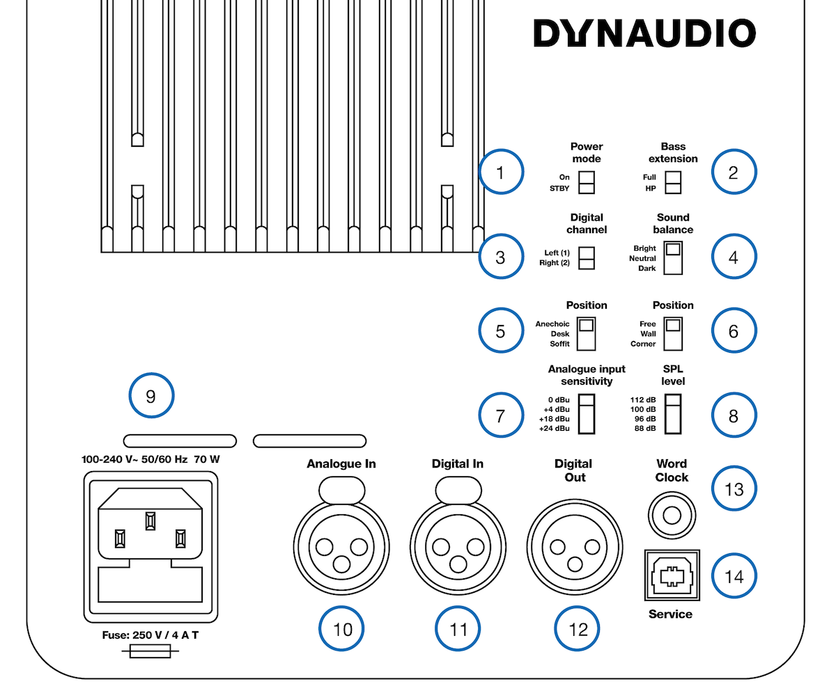
- Power mode: Power-saving auto-standby switch
- Bass extension: sets a Linkwitz-Riley HPF at 80 Hz
- Digital channel: selects the left or right channel of the AES digital input signal
- Sound balance: switches between three tilt filter settings
- Position switch 1: position filters
- Position switch 2: boundary filters
- Analogue input sensitivity: sets the maximum input voltage
- SPL level: sets the SPL for -6 dBFS (-6 dB from selected maximum input voltage)
- AC power Input (100-240 V)
- Analogue in: Balanced analogue input (XLR)
- Digital In: AES digital input (XLR)
- Digital Out: AES digital output – pass through for second monitor (XLR)
- Word Clock: Word Clock input (75 Ω BNC)
- Service: USB Type B for firmware update or service
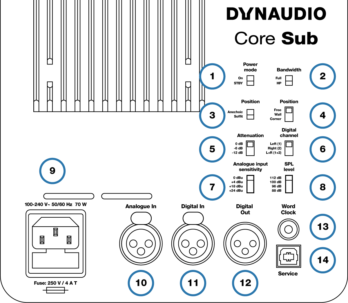
- Power mode: Power-saving auto-standby switch
- Bandwidth: sets a Linkwitz-Riley LPF at 80 Hz
- Position switch 1: position filters
- Position switch 2: boundary filters
- Attenuation: for use with two or four subwoofers
- Digital channel: selects the left, right, or left + right channels of the AES digital input signal
- Analogue input sensitivity: sets the maximum input voltage
- SPL level: sets the SPL for -6 dBFS (-6 dB from selected maximum input voltage)
- AC power Input (100-240 V)
- Analogue in: Balanced analogue input (XLR)
- Digital In: AES digital input (XLR)
- Digital Out: AES digital output – pass through for second monitor (XLR)
- Word Clock: Word Clock input (75 Ω BNC)
- Service: USB Type B for firmware update or service
Positioning the monitors
In order to get the best performance from your Dynaudio monitors, care must be taken when positioning them in the listening environment. The room greatly affects the sound so the position and angle of the monitors relative to the walls, ceiling and floor is critical in any listening environment.
Acoustic axis
The acoustic axis is an imaginary line passing through the centre point on the monitor. As shown in Figure 2, use this method for measuring the distance and angle to your listening position. The point is positioned half the distance between the boundary of the tweeter and the boundary of the woofer or midrange driver.
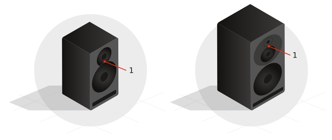
The Core 7 is designed to be positioned vertically and pointed directly at the listener.
The Core 47 has two versions with the woofer on either side of the tweeter and midrange drivers for either horizontal left or right side placement.
The Core 59 is designed to be used in either vertical or horizontal position by rotating the Orbit Baffle.
The Core Sub is a side-firing subwoofer where the front baffle has the logo and LED indicator.
Room boundaries
Each surface in the room constitutes a boundary for sound; floor, walls, and ceiling. Room boundaries will reflect sound to one degree or another depending on the surface material; hardwood, drywall, carpet etc. If possible, please avoid placing monitors very close to any boundaries. The closer a monitor is to a room boundary, the more anomalies you may experience in the low-frequency response of the system. Placing a monitor close to more than one boundary (e.g. in a corner) creates even worse problems in many cases.
Conversely, placing monitors exactly halfway between room boundaries may over-excite fundamental standing waves in the room, making the bass response less reliable. This is also the case with regard to the listening position. These room anomalies are always present, but proper placement of the monitors according to the listening position will reduce their effect.
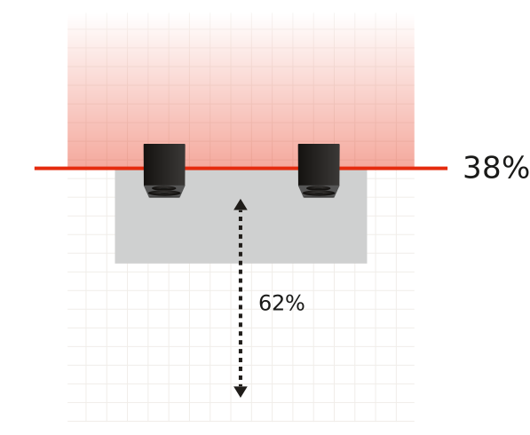
A good rule of thumb is to place monitors somewhere between one quarter and one third of the distance between room boundaries as shown in Figure 3.
Also make sure the listening position is not right in the centre of the room if possible. In larger rooms, this is less critical than in small rooms.
Sometimes, the ideal positioning is not possible to achieve. Limitations in terms of space and other equipment or furniture in the room may influence several aspects of the monitor position. In short, the idea is to do the best you can with the limitations you have.
Listening distance and mounting
The Core 7 monitors are designed as nearfield monitors. Nearfield monitors should be placed relatively close to the listener, between 1 and 3 metres.
The Core 47 and Core 59 can be used both as a near or midfield monitor, positioned between 1.5 to 4 meters.
When used as an LF extension, the Core Sub should be placed with the front baffle at the same distance to the listener as the other monitors. If the Core Sub is used in a surround or immersive setting, follow the guidelines for that application.
Monitors on the desk or console
These monitors are designed to work well in a variety of positions, including when placed closely and on the work surface in front of you. If they are resting on a desk or a console meter bridge, they may be tilted up or down to aim at ear level with great results. The first Position switch should be set to “Desk”.
Monitor stands
Placing your monitors on stands behind your workstation or console is very common and gives you more control over the distance, angle, and position within the room. The first Position switch should be set to “Anechoic” so long as the monitors are not closer than 50 cm from any wall or ceiling.
Core Mounting bracket
The Core Mounting Bracket is designed to facilitate mounting of the Core 7, 47, and 59 either on a wall, ceiling, or even as a desk stand. This bracket is compatible with many standard K&M accessories for more mounting options.
Soffit Mounting
In a soffit mount design, the monitors are placed within cabinets built into the walls of the listening room. This will provide a more phase coherent bass response and better imaging if designed properly. If the Core monitors are soffit mounted, the first Position switch should be set to “Soffit”. This will compensate for the increase in bass output from the soffit design.
When soffit mounting Core monitors, allow 12 mm of space above and below for proper ventilation of the amplifier. The Core Sub requires an additional 50 mm or more of clearance on either side for driver excursion.
Listening angles
Usually, the monitors should be placed so that the drivers are oriented vertically, with the tweeter directly above the woofer or midrange driver. This orientation ensures correct time alignment between the high and mid frequencies as they arrive at the listener. The Core 59 incorporates the Orbit Baffle, which allows the tweeter and midrange assembly to be rotated to multiple orientations so that you are free to place the woofer below, to the side or even above this assembly.
Horizontal angle
The monitors should be placed so that they create a 60-degree angle between the monitors, as shown in Figure 4.

The easiest way to accomplish this without measuring the angle is to create an equilateral triangle between the monitors and the listener. In other words, the distance between each monitor should be equal to the distance from each monitor to the listener. The Core 59 can be positioned with the woofers inside (recommended) or outside, depending on how the equilateral triangle can be achieved best. Make sure to take measurements from the acoustic axis of the monitor.
An easy method to do this involves a measuring tape and some string. With the tape measure, check that the monitors are not placed further away than 3 metres for free field reference listening level.
- Once you have initially placed the monitors, take the string holding one end at the monitor’s acoustic axis and stretch it out to the listening position.
- Measure the distance to a single point behind your head where the strings from both sides would meet.
- Mark this point with a marker.
- Do this again for the other monitor to ensure that they are both the exact same distance from the listener.
- Use the string to measure the distance between each monitor. This should also be the same, forming and equilateral triangle between the two monitors and the listener.
- Make adjustments as necessary to place the listener and monitors at the same distance from each other.
Vertical angle
The vertical angle of the monitors should orient the monitor directly toward the listener’s ear level. If the monitor is placed higher than the listener, they should be angled downward. Conversely, if the monitor is below the listener’s ear level, they can be angled upward to point at the ear as shown in Figure 5.

Monitor orientation
The Core monitors give you the advantage of multiple orientations for each monitor, offering maximum flexibility for proper installation.
Core monitors can be place standing up or on their sides with either the woofers facing out or in. They can also be placed with the woofer on top in case that aligns the tweeter better with the listener’s ear height or improves the bass response of the room.
Note that the Core 47 has two models with the woofer placed on either side of the tweeter/midrange assembly. These monitors should be used in horizontal orientation only.
Hover Pads
The Core monitors come with pads that should be used when placing the monitors regardless of the surface material. Align these pads with the corresponding indentations on each side of the monitor. Using hover pads, you can place the monitor in any desired orientation without marring the surface of the enclosure and allow the monitors to “hover” in their position. They also provide some degree of isolation between the monitor and the mounting surface.
Core 59 and Dynaudio Orbit Baffle
The Core 59’s offer additional benefits, as they incorporate our Orbit Baffle (formerly “221”) that was first used in the renowned Air series of monitors. This technology places the tweeter and midrange driver together in their own self-contained baffle/enclosure that can be rotated inside the larger cabinet to provide additional orientation options.
For example, you may turn the midrange and tweeter assembly 90 degrees in either direction to place the monitor on its side and still have proper time alignment from the tweeter and midrange drivers. For a centre channel monitor, you can position the woofer either below or above the Orbit Baffle for the least obstructive path to the listener. There is no need for separate left, centre, and right channel models as each monitor is capable of operating in any position of a 5.1, 7.1, 9.1.2, or Dolby Atmos surround monitor system.
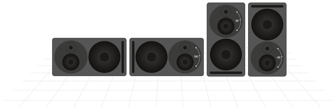
Rotating the Core 59’s Orbit Baffle
See Appendix.
Connecting the monitors
Mains
Ensure that you have the correct three-wire grounding type mains cable for your region. The power supplies in the monitors have switching inputs that automatically adapts to the incoming voltage depending on your location.
Plug in the provided mains cable to the monitor and then to the outlet. Ensure the monitor powers up correctly by checking that the power LED is lit on the front of the monitor. Once this is confirmed, power off the monitor by removing the mains cable from the outlet before connecting audio signals.
Standby mode
The monitors have a standby mode that helps conserve energy when they are not in use.
- When the Power mode switch is set to “ON”, the monitors remain powered on until the mains cable is unplugged.
- When the Power mode switch is set to “STBY”, the monitors will automatically enter a power-saving standby mode when not in use for 20 minutes and shut down the amplifier section until audio is once again detected at the input.
Note
To comply with the European Commission Regulation (EU) No 801/2013 (low standby directive) the Power mode switch must always be set to “STBY”.
Audio signals
There are two physical inputs you can choose between:
- XLR balanced or unbalanced
- XLR AES Digital
Word Clock Input
When using the AES digital input, you may synchronise the digital clock using a word clock signal. The Word Clock connector on the Core monitor should be used in this case to receive a word clock signal that is derived from the AES audio source. This will ensure that the internal clock of the Core monitor is running exactly in sync with the AES audio signal source.
If no word clock signal is present at the Core’s Word Clock input, the Core monitor will use the embedded word clock from the AES signal itself as a synchronisation source. If the word clock is present, but not in sync with the AES clock, the front panel LED will flash bright green and the monitors will mute.
If you are using the Core Sub to extend the frequency response of a single Core monitor, connect the same audio source to both the Core Sub and Core monitor either with the analogue or AES inputs. For the analogue inputs, you will need to use a professional balanced line splitter to feed both the Core Sub and Core monitor analogue inputs.
If using the digital inputs, you can simply daisy-chain the monitors using the digital out connector. Ensure that both the monitor and sub are set to the correct digital channel (L, R, or L + R).

Caution
Before sending audio to the monitors, set the Analogue input sensitivity to 24 dBu and the SPL level switch to 88 dB. Then adjust the outputs of your mixer or audio interface to a low setting and gradually turn up the signal until you get a reasonable volume. This will prevent any accidental overload of the monitor input.
Adjusting the volume
The Core monitors have two inputs – analogue and digital. When using the analogue input, adjust the analogue input sensitivity to adjust the volume of the monitors. When using the digital input, adjust the SPL level to adjust the volume.
Analogue Input Sensitivity
There is a four-position switch that adjusts the analogue input sensitivity for the monitor. Depending on the maximum output level of your mixer, interface, or monitor control system, you can choose a setting that optimises the gain staging into the monitor.
For example, if you are using a professional audio interface or console with a max output of +24 dBu, set the input sensitivity to +24 dBu. If you are using a prosumer type mixer or interface with a maximum output of +18 dBu, then set the input sensitivity to +18 dBu. For consumer equipment such as DJ mixers that operate at a nominal level of -10 dBV, set the input sensitivity to 0 dBu.
0 dBu is the loudest setting while +24 dBu is the softest setting. The range is provided to optimise the signal to noise ratio between the monitoring output and the monitor.
SPL Level
The SPL Level setting determines the volume the monitors will achieve for an input level of -6 dBFS or -6 dB from selected analogue input sensitivity. If you work primarily at low levels, you can use a lower SPL setting to optimise the gain staging of the monitor to achieve the best results. If you work at louder levels, use the maximum 112 dB setting for the greatest volume that the monitor can provide.
Note
The 112 dB setting achieves a free field reference level of 85 dB with +20 dB of headroom at 3 meters distance.
Front LED Indicator
There is one LED indicator on the front that provides information on the status of the Core monitor by glowing or flashing either green or red. The following modes are indicated in this way.
Standby:
The LED turns bright red then fades to 50% after 5 seconds.
Power On:
The LED turns bright green then fades to 50% after 5 seconds.
Amplifier Clipping:
The LED flashes bright red continuously.
Thermal Protection:
The LED pulses red and the output is reduced by 6 dB
Word Clock Error:
When the word clock input is not aligned with the AES input signal, the LED flashes bright green and the monitors are muted.
Input Clipping:
The LED turns orange when the analog to digital converter is clipping.
DSP Settings
Our engineers have painstakingly created a DSP controller for these monitors that lets you tailor the sound to your particular environment. The DSP settings provide precision adjustments that optimise the monitors for their position and mounting within the listening space.
Bass extension
The Core series monitors are designed to handle deep bass by themselves. And under normal conditions, the Bass extension switch should be set to “Full”. However, if you are integrating a Core Sub to extend the bass response even further, set the Bass extension to “HP”. This will engage a 4th order Linkwitz-Riley high pass filter at 80 Hz with time alignment that properly integrates the monitor with the Core Sub.
Bandwidth (Core Sub)
Use the LP setting when integrating the Core Sub to extend the LF response of a Core Monitor. This will engage a 4th order Linkwitz-Riley low pass filter at 80 Hz to integrate the Core Sub with the Core monitor.
Sound balance
The sound balance, or tilt filter, represents a refined way to affect the overall tone of the monitor (not applicable for the Core Sub). Depending on the room treatment and other factors, it may be necessary to make the monitor darker or brighter than the neutral setting. A dead sounding room with a great deal of treatment might need a brighter setting than a lively room with many reflective surfaces. Musical styles and program material may also affect the choice of sound balance as well as personal preference.
Sound Balance offers three settings:
- Bright: 20 Hz -1,5 dB, 20 kHz +1,5 dB
- Neutral
- Dark: 20 Hz +1,5 dB, 20 kHz -1,5 dB
What this filter actually does is to tilt the entire spectrum by 1.5 dB at either end, using minimal phase filter to either brighten or darken the overall response. This minimal filter alters the tonality without inducing audible phase anomalies, thereby maximising the linearity of the monitor.
First Position Switch: Anechoic / Desk / Soffit
Depending upon where your Core monitors are positioned in your room, you can adjust the Core’s DSP to optimise for differing acoustics.
- The “Anechoic” setting is used when the monitors are placed on monitor stands in rooms that have sufficient dampening treatment such as recording studios and film dubbing stages.
- The “Desk” setting is used when the monitors are placed on a workstation or meter bridge of a mixing console (not applicable for Core Sub).
- The “Soffit” setting is used when the monitors are mounted in properly designed wall soffits as part of an overall architectural acoustic design.
Second Position Switch: Free / Wall / Corner
Boundary filters controlled with the second Position switch are used to compensate for monitors that are placed close to walls or in corners where low-frequency room modes can be triggered by the monitor. The Core’s DSP can adjust the response to compensate for either a wall or corner placement.
- If your monitors are placed further than 50 cm from any wall surface, use the “Free” setting.
- If you have positioned your monitors within 50 cm of a wall the position switch should be set to “Wall”.
- If the monitor is placed within 50 cm of a corner, set Position 2 to “Corner.”
These settings will help coping with anomalies created by reflections coming off the back and sidewalls, especially in the lower frequencies.
Listening tests
Once you have your monitors properly positioned, it’s time to start listening to them. Subjective listening tests can be made with reference material that you are familiar with; a favourite album, movie or other recording. Objective tests can be made simply with a smartphone app or a more sophisticated acoustic measurement system.
Reference material
Play some recorded material that you are familiar with through the monitors to see if the sound is how you expected. Adjust the tilt filters in both directions to hear the different tonalities. It is also suggested that you listen to material you know actually sounds bad or has defects in the recordings. A truly neutral monitor will reveal these defects clearly.
A good monitor delivers accurate representation of the sound whether this happens to be good or bad, so that informed mix decisions can be made. Adjust the tilt filter to the setting you are most comfortable with.
Pink noise
For an objective test of the monitor’s response, you will need a metering system. This consists of a device that can measure the spectral output of the monitor in real-time and a source of pink noise that can be played back through the monitors. Pink noise is a balanced level of noise across the entire spectrum. When played back through a proper monitoring system, an RTA should show a flat response in the room.
- RTA Spectral Analyser
- Pink Noise Source
We have created an iOS app with these tools built in so you can quickly test and calibrate your Core monitors using your iOS device. In the Apple App Store, search for ‘Dynaudio Sound Meter’ to download this free app.
Play the pink noise from the Dynaudio Sound Meter app and adjust the level to a reasonable playback volume. If you wish to play pink noise from your computer workstation, a WAV file containing pink noise is available at dynaudio.com/pinknoise.
Play the pink noise through one monitor at a time at a reasonable level (~80-85 dBA) and place the iPhone or iPad at the listening position. Change the Sound balance filter setting to see how the response changes the response curve in the RTA. In the RTA display, the reading should be as even as possible.
If you notice excessive levels in the low frequencies, try setting the Sound Balance filter to “Bright” and check the results. Or perhaps your monitors are too close to a wall and need the Position 2 switch set to “Wall” or “Corner”.
If the spectrum analyser shows a greater degree of high frequencies, set the Sound Balance filter to “Dark” and check the results. Low frequency response can be greatly affected by boundary walls, soffit mounting, and other positioning issues. Experiment with the Position 1 and Position 2 settings and see how the RTA reacts. You can gain valuable insights into the acoustics of your listening room by repeating this process.
Once you have the Position and Sound Balance filters set for the flattest response curve in the RTA, return to your reference material to see how it sounds. Through this process of objective tests with the RTA and subjective listening tests with your ears, you will arrive at the best setting for your Core monitors.
Final tweaks
Beyond the settings for the monitors, additional tweaks may be desired to improve the response of the system and room environment. You may discover that a reflective surface is causing a high frequency anomaly or perhaps room modes are disturbing the bass response.
First reflection treatment
Sound reflecting off hard surfaces that are close to the listening position can cause problems in the high frequency response and imaging of the monitors. In many cases, these first reflections are relatively easy to fix. Figure 7 shows some common causes of first reflections in a typical control room.
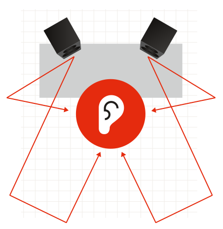
First reflections can be located easily by using a mirror placed on various surfaces in the studio to check if you can see either monitor in the mirror while sitting in the listening position. If you can see either monitor in the mirror, upper frequencies will bounce off that surface directly back to the listening position and potentially cause response problems.
Placing absorptive material on these surfaces will reduce the effect of first reflections and improve the sound of the system. The thicker the acoustic material is, the more effective it will be. Also, creating an air space behind the material will improve its effectiveness. Place as much absorption that is practical at the first reflection points to improve the response of the system.
Bass room modes
If you notice any peaks or dips in the low-frequency response curve of the RTA (20-250 Hz), they are probably caused by room modes. Room modes occur at specific low frequencies that have wavelengths that are equal to or multiples of the dimensions of the listening room.
For example, if the listening room is 4 metres long, there may be a room mode at 43 Hz since its wavelength is about 8 meters. What this means is that for this frequency, the room response will change dramatically depending on the position of the listener and the monitor. You may hear more of this frequency or less of it depending on the listening position in the room. Modes can be formed from all dimensions of the room; length, width, and height so it can get complicated.
Try moving the positions of the monitors and also the listener to see if you can improve the overall bass response. This will take some experimentation time and is often surprising when the best placement is found. Another solution is to place sound absorption designed for low frequencies in the most effective places to reduce the effect of room modes (often in the corners).
Many manufacturers make sound-absorptive devices called bass traps that are designed to be placed in or near corners and will reduce the amount of reflected low-frequency energy in the room. By dampening the resonance of the modes, the low-frequency response of the room may be smoothed out.
When placing bass traps, always check the resulting frequency response curve either with pink noise and an RTA or by listening to your favourite reference material to see how this affects the sound.
Through this process of trial and error, you will arrive at the best position and treatment for your environment. You will get the most out of your Dynaudio Core monitor system, allowing you to create music and sound that translates to as many other listeners as possible. Enjoy!
Updating the firmware
Core Update Tool
Periodically you may need to update the firmware in your Core monitors. This is done using the Core Update Tool found here: dynaudio.com/support. The download package includes software for both macOS and Windows.
- Download and extract the ZIP file. Inside the folder you will find two applications, one for Mac and another for Windows.
- Place the application in the appropriate location for your computer.
USB 2.0 connection
You will also need a USB 2.0 connection between your computer and the Core monitor in order to update the firmware. Each Core monitor has a female USB type B connector on the back panel.
Firmware update process
- To update the firmware, first ensure that the Core monitor is turned on.
- Connect your computer and the USB jack on the monitor’s back panel using a USB cable.
- Launch the Core Update Tool.
Caution
You may have to change your security preferences to allow the Core Update Tool to run on your computer.
Choose the “Firmware update” option, and you will see this window:
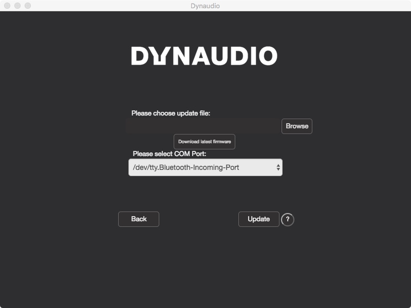
Choose the COM port that is connected to the Core monitor. As port names may be random and not obvious, try selecting each one until you see that a Core monitor is recognized. You will see the Core model displayed along with the current version of firmware that is installed.
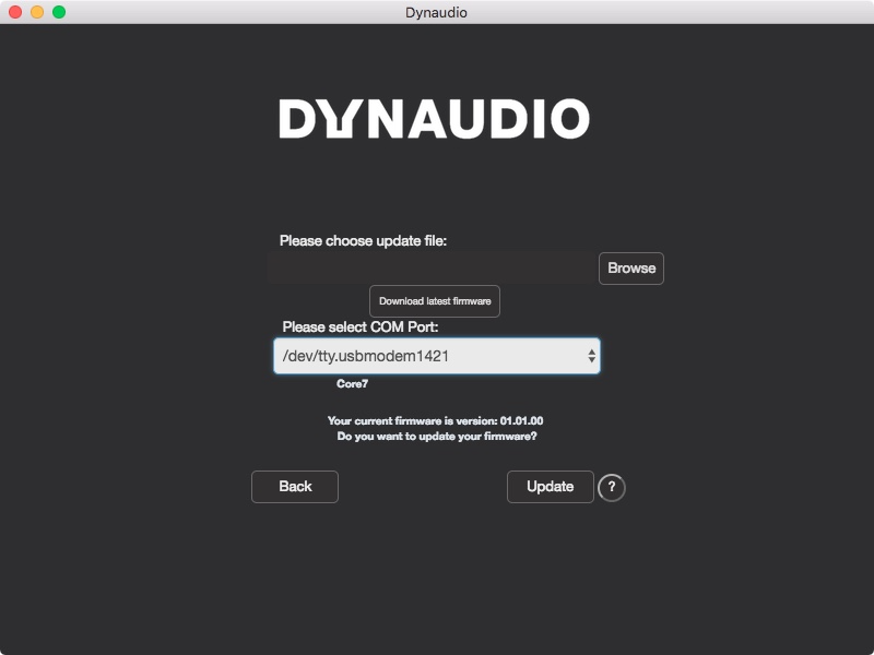
Next, download the latest firmware by clicking the “Download latest firmware” button.
Once the download has finished, the message “Download successful” will appear in the update file field. You are now ready to upload the latest firmware into your Core monitor. Ensure that during this process the power is not disconnected at any time, or permanent damage may occur to your monitor.
Click the Update button. A progress bar will appear showing the status of the upload.
Once the upload has finished, you can simply disconnect the USB cable, and your Core monitor is ready to use.
If you are updating multiple monitors, click “Next speaker” to continue.