Sub RCC
Dynaudio custom install limited warranty
Dynaudio warrants its custom install products to be free from defects in materials and workmanship under conditions of normal use and service for a lifetime period from the date of original purchase. For this warranty to apply, the unit must be installed and used according to its written instructions.
The obligation under this warranty shall be limited to the replacement, repair or refund of any such defective device within the warranty period, provided that:
- inspection by Dynaudio indicates the validity of the claim;
- the defect is not the result of damage, misuse, lightning, power surges, negligence, improper operation (installation) or failure to follow instructions contained in the manual or written instructions provided by Dynaudio after the original purchase;
- the product has not been altered in any way or repaired by others and that factory sealed units are unopened (a service charge plus parts and labour will be applied to units defaced or physically damaged);
- the dealer from whom the Dynaudio products were purchased was authorized to sell such products at the time of the original purchase;
- the service provider for, including but not limited, installation or repair of the product, was authorized in writing by Dynaudio;
- the original, dated Bill of Sale is presented whenever service is required during the warranty period;
- freight charges for the return of products to Dynaudio are prepaid;
- all units ‘out of warranty’ are subject to a service charge. The service charge will cover minor repairs (major repairs will be subject to additional charges for parts and labour).
This warranty is in lieu of and excludes all other warranties, expressed or implied. Neither this warranty nor any other warranty, express or implied, including implied warranties of merchantability and fitness, shall extend beyond the warranty period.
Dynaudio shall not be liable for damages to any other equipment or other items at the site of use, or any other damages whether incidental, consequential or otherwise. Dynaudio shall not be liable for any anticipated profits, any incidental or consequential damages, loss of time or other losses incurred by the purchaser in connection with the purchase, operation or use of the product.
The information this document contains is subject to change without notice. In the event that there are differences between this warranty and the provisions of any advertisements, documentation, product brochures or packaging cartons, the terms of this warranty shall prevail.
Introduction
Welcome to the Sub RCC in-wall subwoofer, and thank you for choosing a Dynaudio Custom Install product.
The Sub RCC is designed to provide concealed low frequency enhancement while at the same time incorporating features and facilities designed to ease installation.
This manual describes the installation of the Sub RCC. The manual begins by illustrating the contents of the carton and continues with sections covering selection of subwoofer positions, subwoofer preparation and subwoofer installation.
If this is your first time working with a Sub RCC subwoofer, or if you have not done so for a while, we recommend that you read this manual before you begin.
Note
Visit dynaudio.com for the latest Sub RCC news and information.
The Dynaudio Custom Install Sub RCC is designed to provide very high quality low frequency enhancement in custom installations where speakers are required to be concealed within room boundaries. The Sub RCC incorporates horizontally opposed drivers that ensures minimal vibrational energy is transmitted to the room structure.
The Sub RCC is primarily intended to be installed within drywall/plasterboard walls however it can in some circumstances be installed within ceilings. Each Sub RCC requires a dedicated AudioControl S500G4 power amplifier that incorporates the appropriate equalisation.
The Sub RCC is uniquely simple to install in either existing (retro-fit) or newly constructed (pre-fit) drywall/plasterboard walls. If a Sub RCC is to be installed within a ceiling, this must only be carried out in either a newly constructed ceiling or following removal of the plasterboard around the install location in order that the Sub RCC can be secured to the ceiling joists.
The Sub RCC requires appropriate mechanical configuration depending on its retro-fit or pre-fit installation mode. Configuration is described in the following Preparation section of this manual.
These instructions broadly assume that for retro-fit installation, appropriate cables are in place, or that for pre-fit installation cables will be fitted at the same time as the subwoofer.
Carton Contents
The In-Wall Sub carton contents is illustrated in Diagram 1 below. Within each carton can be found:
1 x Subwoofer unit with retro-fit adaptors attached
- 4 x Pre-fit Mounting Brackets
- 8 x M6 x 8 mm Pre-fit Mounting Bracket screws
- 6 x Ø4.5 mm x 45 mm wood screws
- 4 x Pre-fit Grille Magnet Strips
- 1 x Retro-fit square grille
- 1 x Pre-fit rectangular grille
- 1 x Retro-fit cut-out template
- 1 x Pre-fit cut out template
- 1 x Document pack
Diagram 1. Carton Contents

Subwoofer Positioning
The appropriate location for Sub RCC in-wall subwoofers within the installation space will depend on the specific audio application. Guidelines for different applications are described in the following sections and illustrated in the accompanying diagrams.
Generally, locating any subwoofer closer to room corners will increase the volume of bass it generates. Although the extra bass can be compensated for by reducing the volume level of the subwoofer relative to the rest of the system, corner locations can also result in uneven bass response at the listening position. In most cases, subwoofers are best located below head height when sitting.
Stereo Audio
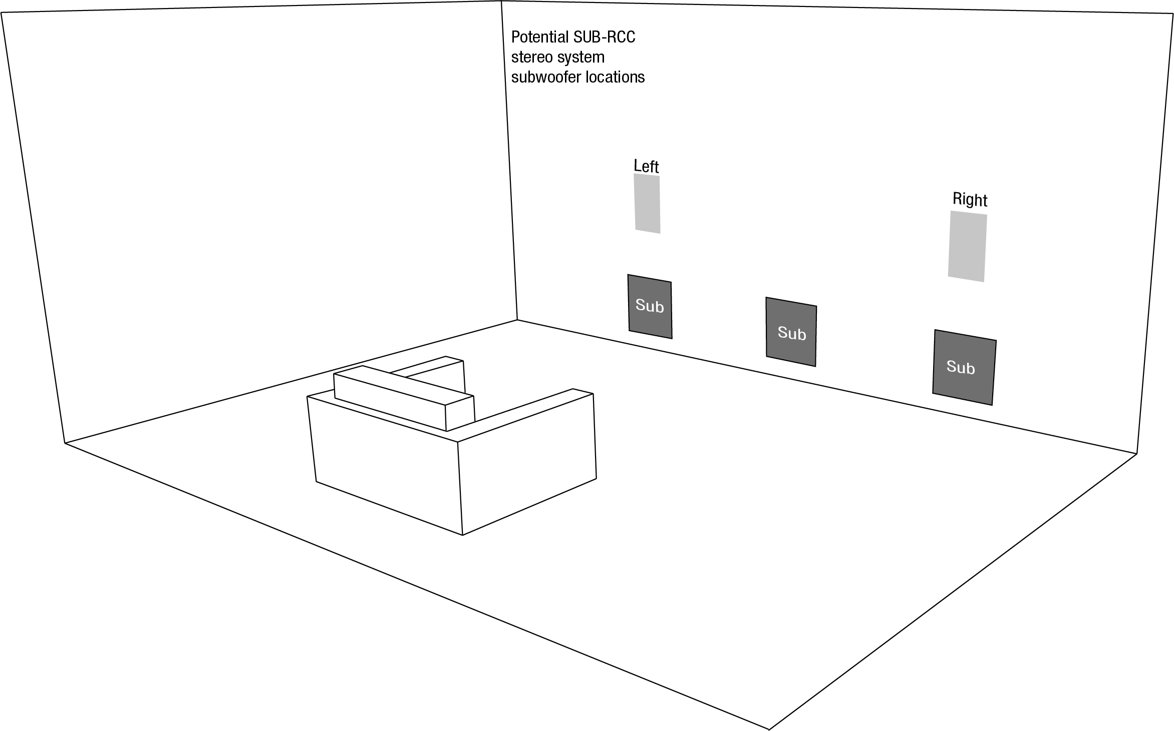
A single Sub RCC used for low frequency enhancement in stereo audio systems should ideally be located centrally between the left and right speakers but asymmetrically with respect to the side walls of the room. If a location between the speakers is not practical, a location adjacent to one of the speakers can also be feasible, however it is important that the Sub RCC is not located too close to a room corner.
If twin (left and right) Sub RCC subwoofers are to be used with a stereo audio system, each one should be located as close as possible to its respective main (left or right) speaker. If this is not practical, the two subwoofers should be located close together either between the front left and right speakers or adjacent to one.
Stereo audio system subwoofer positioning is illustrated in Diagram 2 below.
Diagram 2. Stereo Audio System Subwoofer Positioning
Home Theatre Audio
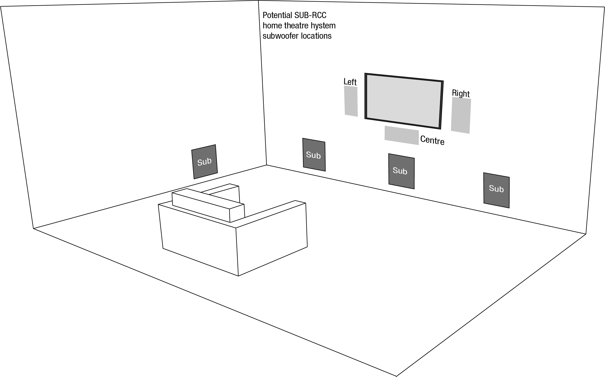
An Sub RCC subwoofer used for the low frequency effects channel in a home theatre system is best located between the left and right channel speakers or adjacent to one of them. If these locations are not practical the Sub RCC can be located along one of the side walls of the listening room, however it should always be located in front of the listening area.
Home theatre system subwoofer positioning is illustrated in Diagram 3 below.
Diagram 3. Home Theatre System Subwoofer Positioning
Preparation
Pre-fit or Retro-fit
The Sub RCC is configurable for installation in either newly constructed (pre-fit) or existing (retro-fit) drywall/plasterboard walls.
Note
In addition to wall installation, the Sub RCC can potentially be installed in newly constructed ceilings (pre-fit). It is NOT suitable for retro-fit ceiling installation. Follow the pre-fit in-wall installation instructions in the case of ceiling installation.
Note
Pre-fit Sub RCC installation can also include existing walls from which the plasterboard has been removed.
As shipped, the Sub RCC is configured in retro-fit mode and can be installed in existing drywall/plasterboard walls without modification. If a Sub RCC is to be installed in the this manner, the following section of this manual may be disregarded.
If a Sub RCC is to be installed in pre-fit mode in a newly constructed drywall/plasterboard wall (i.e. before the plasterboard is fitted) it must be configured appropriately. Pre-fit configuration is described in the following section.
Pre-fit Sub RCC Configuration
- To configure a Sub RCC for pre-fit installation, its Retro-fit Adaptor Plates must be removed and the four supplied Pre-fit Mounting Brackets must be attached. These procedures are described and illustrated in the following paragraphs and diagrams.
- To remove the two Retro-fit Adaptor Plates, unscrew and remove the eight retaining screws illustrated in Diagram 4. The Retro-fit Adaptor Plates will lift away from the subwoofer body when the screws are removed and the snap locks located behind the yellow clamps are released.
- Retain the adaptor plates and screws for possible later use.
Diagram 4. Retro-fit Adaptor Plate Removal

To attach the Pre-fit Mounting Brackets identify the eight attachment screw holes in the sides of the subwoofer body and the eight M6 x 15 mm screws supplied. Attach the brackets using the screws as illustrated in Diagram 5. Do not fully tighten the screws at this stage.
Note
Pre-fit Mounting Bracket screw holes are located on the end and side panels of the subwoofer. Either option may be used depending on the requirements of the installation.
Diagram 5. Pre-fit Mounting Bracket Attachment

Installation Dimensions
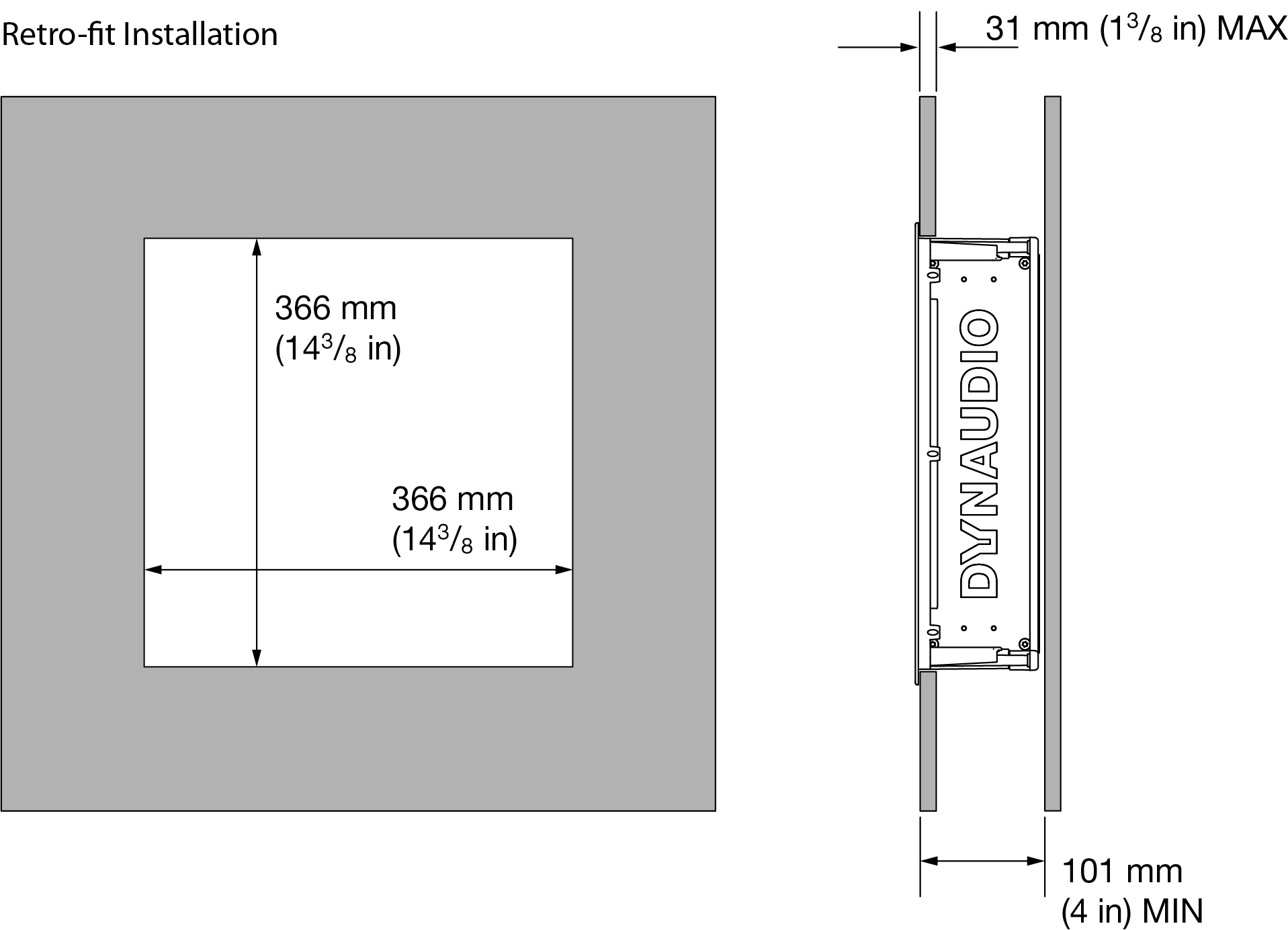
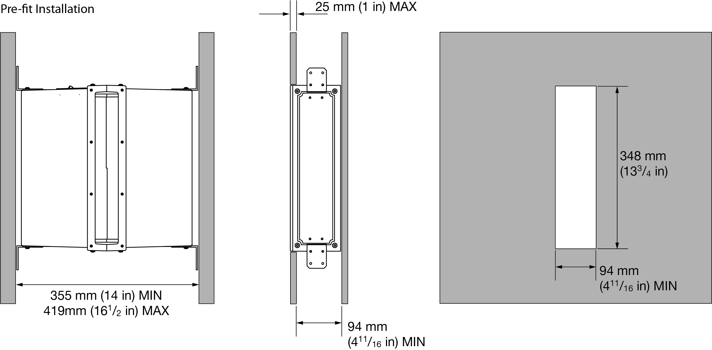
The in-wall space required for Sub RCC installation is described and illustrated in the following table and in Diagram 6.
Retro-fit Dimensions
- Wall Cut-out Size:
366 x 366 mm
(143⁄8 in x 143⁄8 in) - Minimum Clear Depth:
93 mm
(311⁄16 in) - Maximum Drywall (Plasterboard) thickness:
X =25 mm
(1 in)
Pre-fit Dimensions
- Minimum Wall Stud Spacing:
354 mm
(14 15⁄16 in) - Maximum Wall Stud Spacing:
415 mm
(161⁄3 in) - Minimum Internal Clear Space:
100 mm
(315⁄16 in)
Diagram 6. Sub RCC Installation Dimensions
Sub RCC Subwoofer Installation
Note
These installation instructions broadly assume that subwoofer cable is pre-installed.
Retro-fit Installation
To install a Sub RCC subwoofer in an existing drywall/plasterboard wall, proceed as described in the following paragraphs and accompanying diagrams:
- Selected the installation position. Check for the presence of studs (joists), pipe work, ducts or cables.
- Mark a cut-line on the wall using the supplied template. Make sure that the dimensions of the cut-line are correct:
366 x 366 mm
(143⁄8 in x 143⁄8 in). - Use an appropriate tool to cut along the cut-line to create a cut-out in the wall.
- Trial fit the subwoofer in the cut-out to check clearances.
Note
In order to reduce the possibility of audible wall vibration it may be prudent to apply a bead of adhesive mastic between the wall studs and the drywall (plasterboard) in the vicinity of the subwoofer.
Note
If subwoofer cable is not already installed it should be done at this stage. It is possible that access will be required through the opposite side of the wall to route the cable. Use low resistance subwoofer cable with clear polarity marking on its insulation. Low resistance is especially important if the length of cable from amplifier to subwoofer exceeds 5 metres. Your local Dynaudio retailer or distributor will be able to offer advice on subwoofer cable selection if required.
- The length of free cable should be sufficient to allow the subwoofer to be connected while outside the wall.
- The cable can now be connected to the subwoofer. Strip 15 mm insulation from the cable (if necessary), twist the wire strands and insert the stripped ends into the subwoofer spring terminals. Ensure that the positive conductor is connected to the red subwoofer terminal and the negative conductor is connected to the black subwoofer terminal.
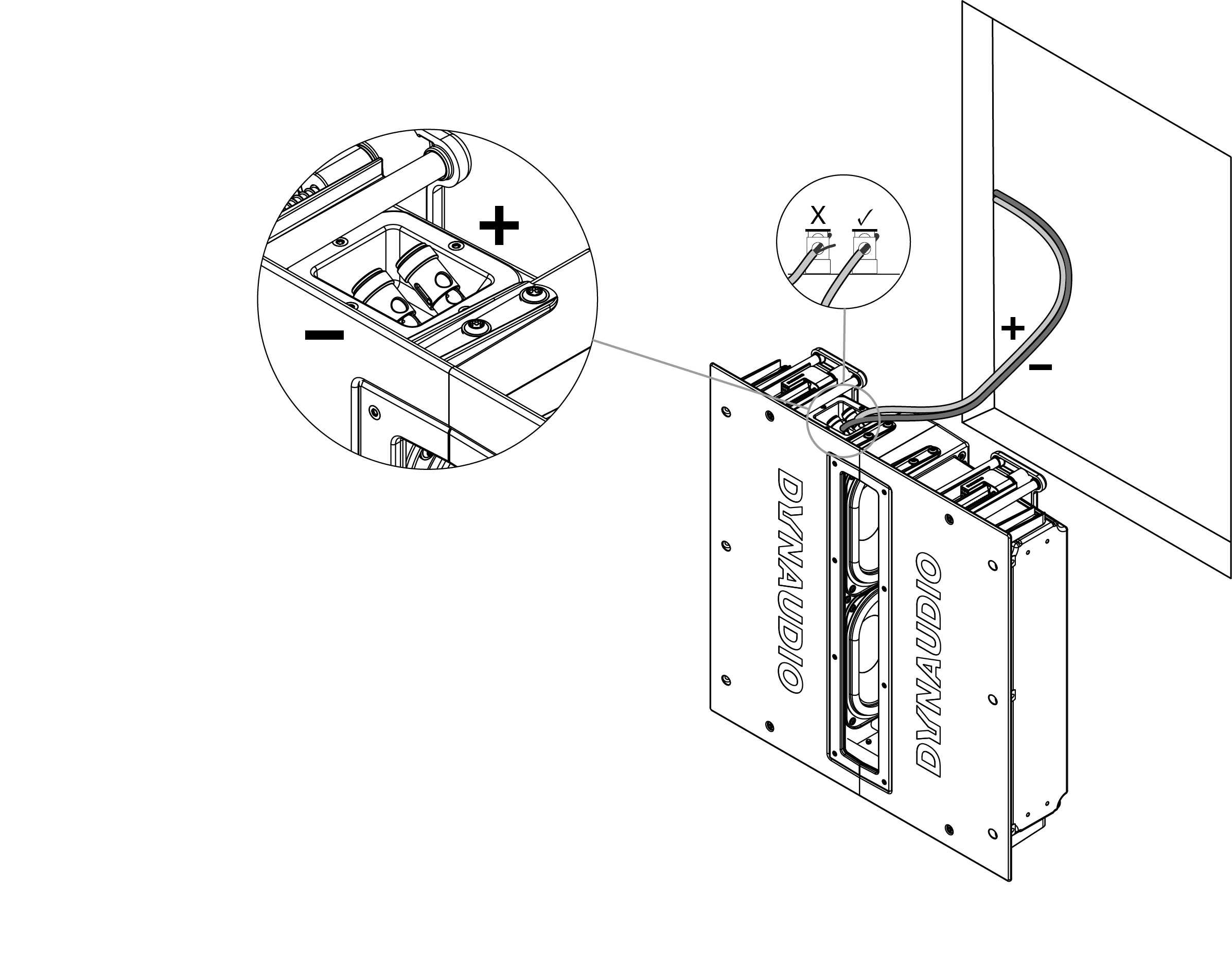
- With the cut-out checked and the cable connected, the subwoofer can be installed. Insert the subwoofer into place and while holding it against the wall with one hand use the other hand to turn the four cross-head screws clockwise untill they are tight. Do not over-tighten the screws. Turning the screws first rotates the four internal securing clamps and then moves them inwards to secure the subwoofer against the inner surface of the drywall (plasterboard).
Note
In cases where the subwoofer is installed within a nominal 16 inch (496 mm) stud pitch wall, additional installation security can be obtained by using the six supplied Ø5 x 45 mm wood screws. The wood screws should be inserted at a 45° angle in the six subwoofer front flange holes and tightened through the plasterboard to engage with the stud woodwork beneath.

With the subwoofer connected and secured in the wall, installation is completed by fitting the grille. The grille is secured magnetically and requires no more than placing into position.

Pre-fit Installation
Note
If a Sub RCC is to be used in a “pre-fit” installation it will require appropriate configuration. Pre-fit configuration is described and illustrated in the Preparation section of this manual.
To install a Sub RCC subwoofer in a newly constructed drywall/plasterboard wall, or in an existing wall from which the plasterboard has been removed, proceed as described in the following paragraphs and accompanying diagrams:
- Having selected the installation position check that the wall studs to which the subwoofer is to be fixed are spaced appropriately. They need to be between
354 mm
(14 15⁄16 in) and
415 mm
(161⁄3 in) apart. - Slide the Pre-fit Mounting Brackets previously attached to the Sub RCC to the appropriate positions to fit the subwoofer centrally between the stud spacing. Tighten the bracket fixing screws.
- Fix the Sub RCC between the wall studs using appropriate screws inserted through the Pre-fit Mounting Brackets into the wall studs. Fix the upper mounting brackets first. Do not use less than sixteen screws (four per bracket). Ensure that the subwoofer output slot is facing outwards.
- The cable can now be connected to the subwoofer. Strip 15 mm insulation from the cable (if necessary), twist the wire strands and insert the stripped ends into the subwoofer spring terminals. Ensure that the positive conductor is connected to the red subwoofer terminal and the negative conductor is connected to the black subwoofer terminal.

- Sub RCC pre-fit installation is completed by fitting the plasterboard, leaving a subwoofer output slot. However, if the build schedule means there is likely to be a significant delay before this final stage, the subwoofer drivers should be protected from the risk of damage or foreign body ingress. This can be achieved by temporarily fitting the rectangular pre-fit subwoofer grille. The grille is secured magnetically and requires no more than placing into position.
- When the plasterboard is fitted to the wall, an appropriate subwoofer output slot must be cut. The output slot cut dimensions are:
86 mm
(33⁄8 in) X
348 mm
(133⁄4 in). It is important that the slot cut in the plasterboard aligns accurately with the subwoofer output slot.
It is also important that the Sub RCC grille is trial fitted before the plasterboard is secured in place. This is to ensure that the magnet strength is adequate to retain the grille and will depend on both the thickness of the plasterboard and how deep into the wall the subwoofer is located. If greater magnet strength is required for secure grille retention, two or four of the supplied magnet strips can be fitted to the long sides of the Sub RCC output slot.

- With the subwoofer connected and secured in the wall, and with the plasterboard fitted, installation is completed by fitting the grille. The grille is secured magnetically and requires no more than placing into position.
Note
If the wall is to be painted following Sub RCC installation, the subwoofer must be protected from paint ingress. If a Sub RCC grille is to be painted, this should be done before is is fitted.