Performance Series
Dynaudio custom install limited warranty
Dynaudio warrants its custom install products to be free from defects in materials and workmanship under conditions of normal use and service for a lifetime period from the date of original purchase. For this warranty to apply, the unit must be installed and used according to its written instructions.
The obligation under this warranty shall be limited to the replacement, repair or refund of any such defective device within the warranty period, provided that:
- inspection by Dynaudio indicates the validity of the claim;
- the defect is not the result of damage, misuse, lightning, power surges, negligence, improper operation (installation) or failure to follow instructions contained in the manual or written instructions provided by Dynaudio after the original purchase;
- the product has not been altered in any way or repaired by others and that factory sealed units are unopened (a service charge plus parts and labour will be applied to units defaced or physically damaged);
- the dealer from whom the Dynaudio products were purchased was authorized to sell such products at the time of the original purchase;
- the service provider for, including but not limited, installation or repair of the product, was authorized in writing by Dynaudio;
- the original, dated Bill of Sale is presented whenever service is required during the warranty period;
- freight charges for the return of products to Dynaudio are prepaid;
- all units ‘out of warranty’ are subject to a service charge. The service charge will cover minor repairs (major repairs will be subject to additional charges for parts and labour).
This warranty is in lieu of and excludes all other warranties, expressed or implied. Neither this warranty nor any other warranty, express or implied, including implied warranties of merchantability and fitness, shall extend beyond the warranty period.
Dynaudio shall not be liable for damages to any other equipment or other items at the site of use, or any other damages whether incidental, consequential or otherwise. Dynaudio shall not be liable for any anticipated profits, any incidental or consequential damages, loss of time or other losses incurred by the purchaser in connection with the purchase, operation or use of the product.
The information this document contains is subject to change without notice. In the event that there are differences between this warranty and the provisions of any advertisements, documentation, product brochures or packaging cartons, the terms of this warranty shall prevail.
Introduction
Welcome to the custom install Performance Series and thank you for choosing a Dynaudio Custom Install product.
The Performance Series comprises the P4-C65, P4-DVC65 and P4-C80 in-ceiling speakers and the P4-W65, P4-W80 and P4-LCR50 in-wall speakers.
Each is designed to offer high quality audio performance while at the same time incorporating features and facilities designed to ease installation.
This manual describes the installation of Performance Series speakers within drywall/plasterboard walls and ceilings. It begins by listing the contents of the Performance Series cartons and continues with sections that provide information common to in-ceiling and in-wall speakers. Later sections in the manual provide information specific to installing in-ceiling or in-wall speakers.
If this is your first time working with Dynaudio Performance Series custom install speakers, or if you have not done so for a while, we recommend that you read the appropriate sections of this manual before you begin.
Note
Visit dynaudio.com for the latest Performance Series news and information.
The Performance Series is designed to provide very high quality audio in custom installations where speakers are required to be fitted flush in walls and ceilings. The Performance Series not only benefits from four decades of Dynaudio speaker expertise but has been designed from first principles to offer a new approach to custom speaker installation and performance.
Performance Series speakers are uniquely simple to install. Once a ceiling or wall cut-out is created, few tools are required and installation can be completed by one person without assistance. Every element of the Performance Series installation procedure, from unpacking the speakers to painting and fitting the magnetic grilles is simplified and streamlined by design.
Performance Series speakers employ numerous Dynaudio speaker technologies, borrowed from the company’s recording studio monitors and high-end hi-fi speakers, to bring genuinely high performance audio to custom installations: unique bass/mid drivers with large diameter aluminum voice coils and finite element optimized high-power, low-distortion magnet systems, proprietary MSP (Magnesium Silicate Polymer) diaphragms, and precision coated soft dome tweeters with powerful neodymium magnet systems are just a few examples among many.
The P4-DVC65 in-ceiling speaker incorporates twin tweeters and a dual voice-coil bass/mid driver that enable it to reproduce both channels of stereo program material.
Performance Series in-ceiling speakers comprise a Speaker Module and Installation Frame. The Installation Frame is inserted into the ceiling cut-out and securely fixed in place using auto-locking clamps. The Speaker Module is then connected to the speaker cables before being inserted into the Installation Frame to be held in place by a turn to latch system. The grille is then fitted, securely attached by magnets integrated within the Installation Frame.
Performance Series in-wall speakers comprise an integrated speaker and installation frame. The integrated unit is connected to the speaker cables before being inserted into the wall aperture where it is secured by clamps tightened through turning cross-head screws located in the unit’s front bezel. The grille is then fitted, securely attached by magnets integrated within the speaker bezel.
Carton Contents
The carton contents for all Performance Series in-ceiling and in-wall speakers are essentially the same. Items only differ in terms of ceiling/wall format and dimension. Within each carton can be found:
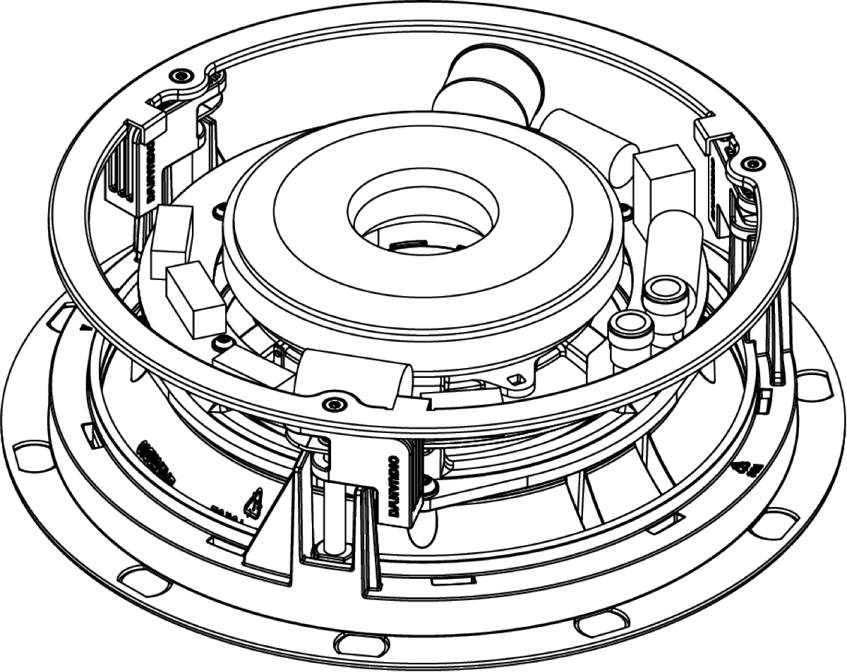
1 x Speaker Unit
1 x Grille
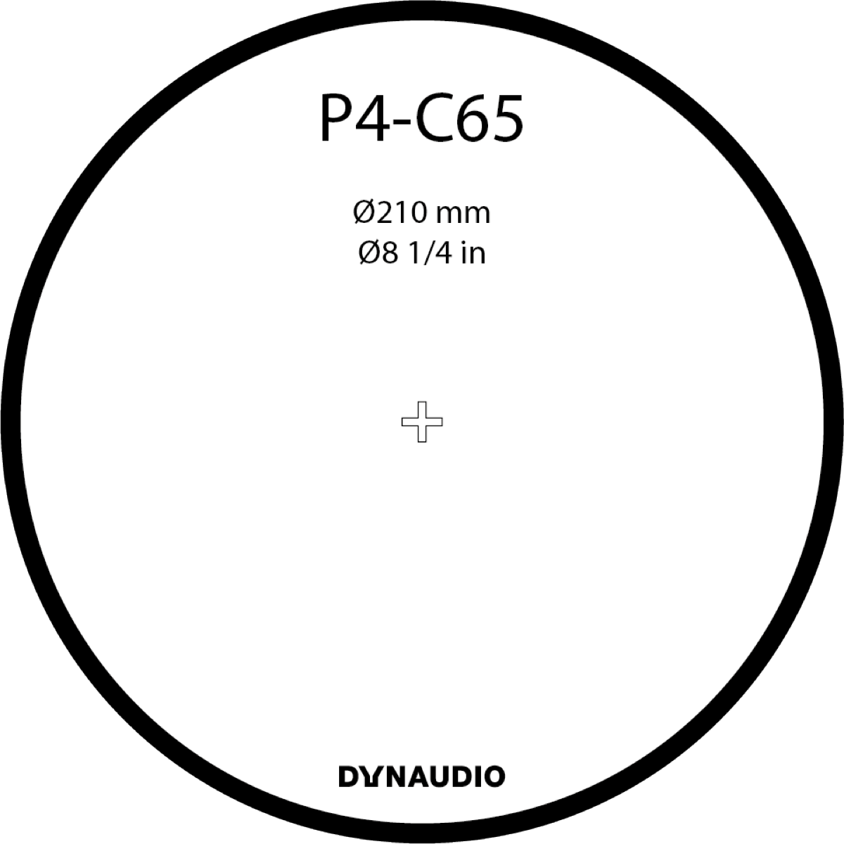
1 x Cut-out Template
1 x Document pack
Note
Square grilles are optionally available for Performance Series in-ceiling speakers. Contact Dynaudio directly or your local retailer/distributor for more information.
Note
Diagram illustrates in-ceiling speaker pack contents. In-wall pack contents are equivalent.
Preparation
Dimensions
Each Performance Series speaker requires specific ceiling or wall cut-out dimensions, mounting depth space and drywall (plasterboard) thickness constraints. These dimensions are tabulated below and illustrated in Diagram 2.
P4-C65 & P4-DVC65
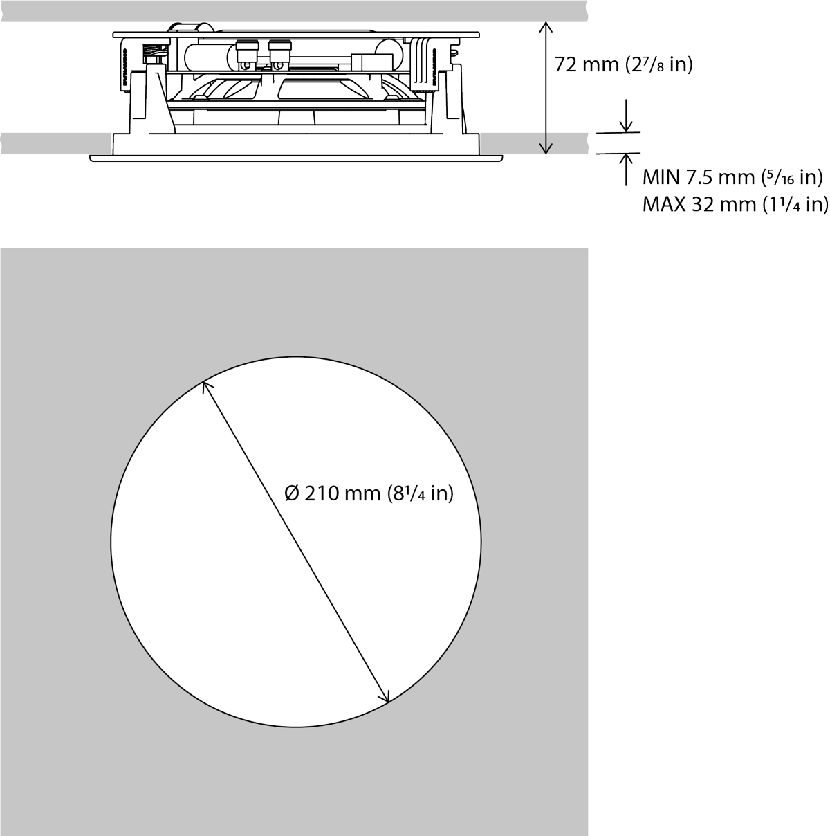
- Cut-out size:
210 mm
(81⁄4 in) - Minimum Clear Depth:
72 mm
(27⁄8 in) - Drywall (Plasterboard) thickness:
X = 32 mm max
7.5 mm min
11⁄4 in max
5⁄16 in min
P4-C80
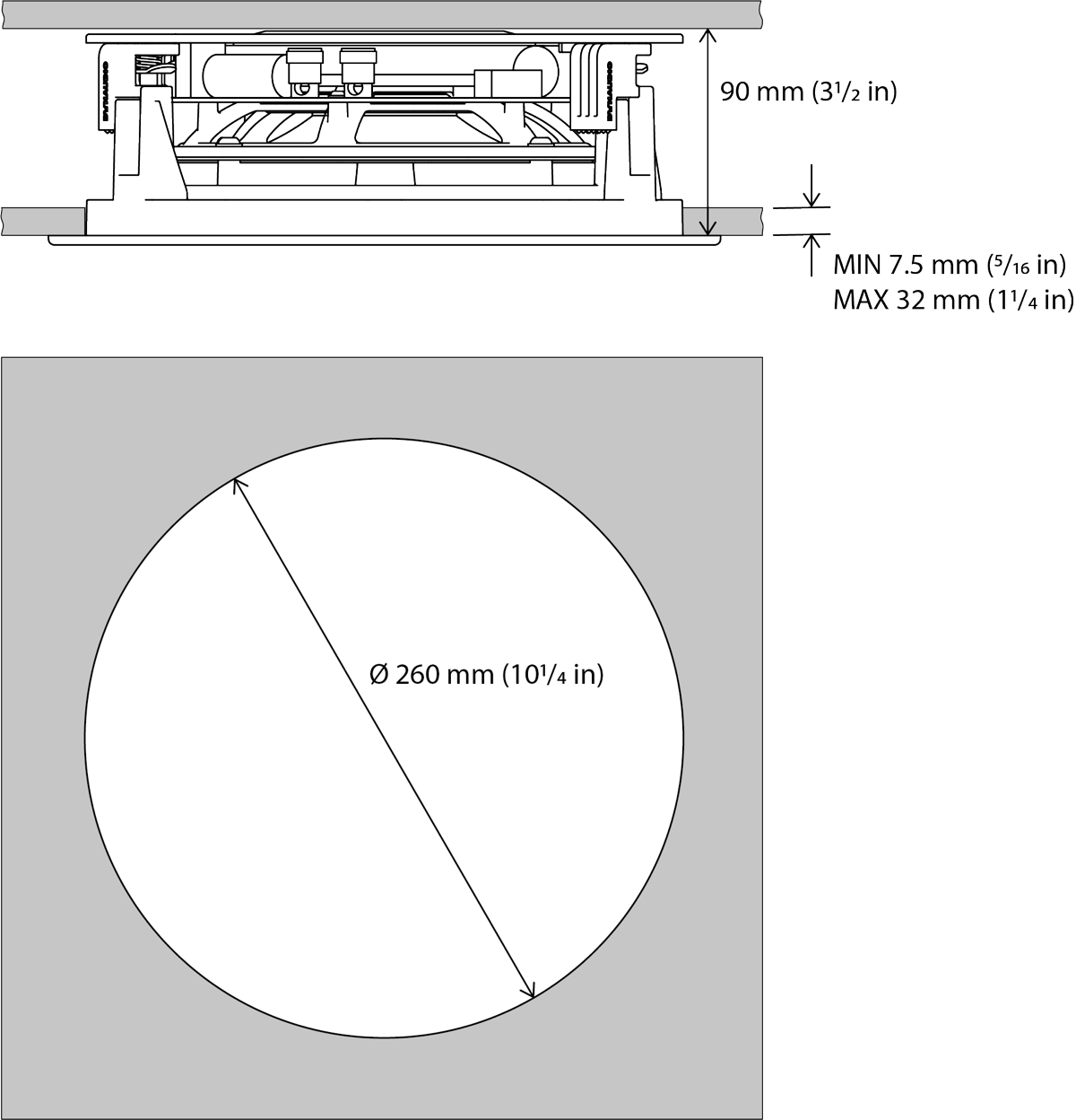
- Cut-out size:
260 mm
(101⁄4 in) - Minimum Clear Depth:
90 mm
(31⁄2 in) - Drywall (Plasterboard) thickness:
X = 32.0 mm max
7.5 mm min
11⁄4 in max
5⁄16 in min
P4-W65

- Cut-out size:
175 mm x 274 mm
(67⁄8 x 10³⁄16 in) - Minimum Clear Depth:
67 mm
(23⁄5 in) - Drywall (Plasterboard) thickness:
X = 32.0 mm max
7.5 mm min
11⁄4 in max
5⁄16 in min
P4-W80
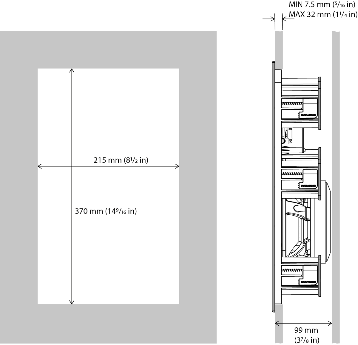
- Cut-out size:
215 mm x 370 mm
(81⁄2 x 149⁄16 in) - Minimum Clear Depth:
99 mm
(37⁄8 in) - Drywall (Plasterboard) thickness:
X = 35.5 mm max
8.8 mm min
13⁄8 in max
3⁄8 in min
P4-LCR50

- Cut-out size:
175 mm x 339 mm
(67⁄8 x 131⁄3 in) - Minimum Clear Depth:
78 mm
(31⁄8 in) - Drywall (Plasterboard) thickness:
X = 32.0 mm max
7.5 mm min
11⁄4 in max
5⁄16 in min
Back Boxes
Performance Series speakers can be installed with back boxes in order to reduce sound transmission into adjacent rooms or to satisfy any local statutory building regulations. If back boxes are to be used they must be installed within the walls and ceilings before the drywall (plasterboard) is affixed to the studs or joists. Alternatively, the existing drywall (plasterboard) around each speaker installation position may be removed to enable a back box to be installed, and reinstated following back box installation. Further information on Dynaudio back boxes can be found at dynaudio.com.
Generic back boxes from alternative manufacturers can be used, or back boxes may be constructed on site. In either case, Performance Series speakers require a 30 Litre (1.1 ft3) minimum back box volume in order to reach their full audio performance potential.
Before commencing any Performance Series installation you must be sure that the wall and ceiling positions chosen are free of obstructions such as pipe work, ducting or wiring that might interfere with the installation. Stud-finding, pipe detecting and wire detecting tools can help map the wall construction and identify any potential obstructions.
CAD drawings for Dynaudio Custom Install back boxes
- In-wall: dynaudiodata.blob.core.windows.net/media/6556/30l-in-wall-wood-backbox.pdf
- In-ceiling: dynaudiodata.blob.core.windows.net/media/6555/30l-in-ceiling-wood-backbox.pdf

Check with local building regulations for fire safety. In some areas it is required to have a fire-rated back box as a fire safety barrier. Ensure that the surrounding materials meet the flammability Class 5VA. A fire rated metal back box must have a minimum uncoated thickness of 1.35 mm.
Speaker Positions
The appropriate positions for Performance Series speakers within the installation space will depend on their application. Position guidelines and diagrams for Performance Series in-ceiling and in-wall models are covered in the following sections and illustrated in the accompanying diagrams.
Background Audio
In-ceiling and In-wall Speakers: If one or more Performance Series speakers are required simply to provide mono background audio, they can be located essentially as dictated by coverage, convenience and architecture. The primary acoustic constraint to consider is that corner positions are likely to result in bass emphasis.
The S4-DVC65 in-ceiling speaker is particularly suited to background sound applications as it can play stereo audio from a single unit.
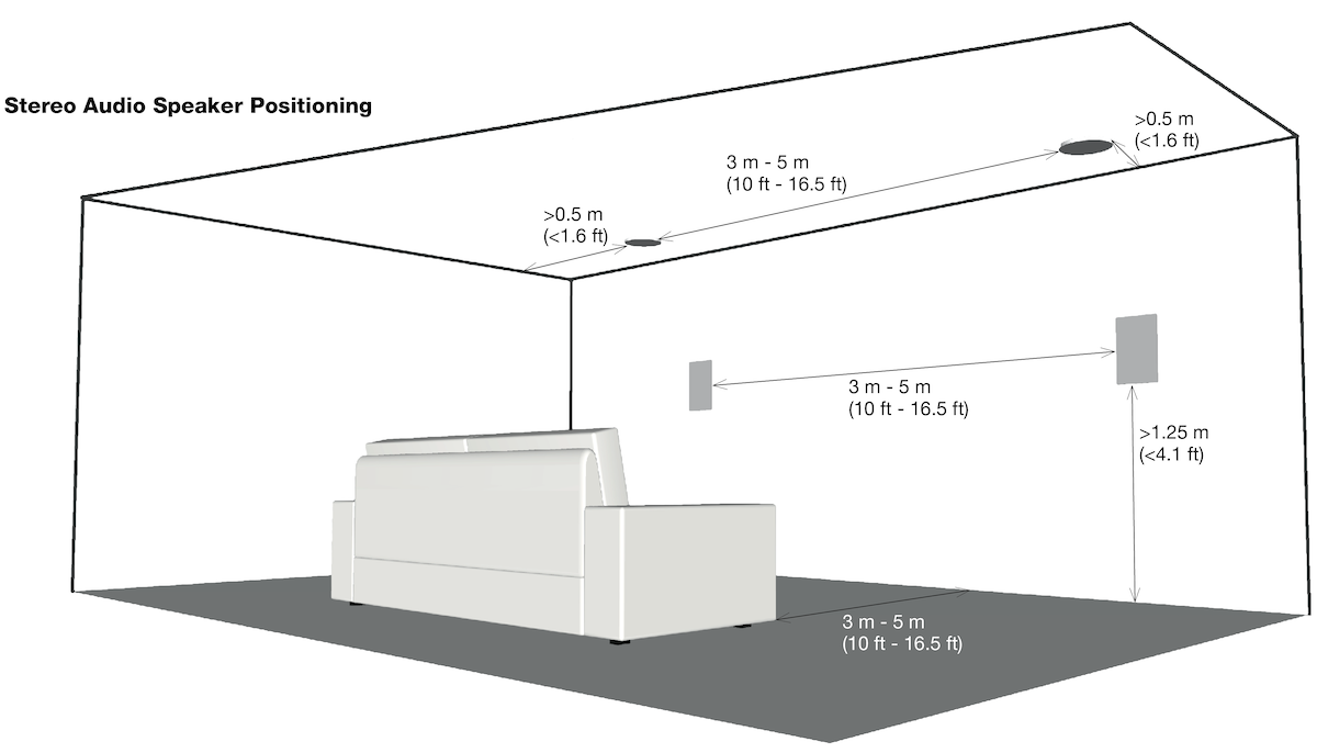
Stereo Audio
In-ceiling Speakers
If a pair of Performance Series in-ceiling speakers are required for stereo audio reproduction, they should ideally be located between 3 m (10 ft) and 5 m (16.5 ft) apart and a similar distance from listening area.
Note
The S4-DVC65 in-ceiling speaker can also be used to reproduce stereo audio thanks to its twin tweeter and dual voice-coil format. Single S4-DVC65 units are however unable to create conventional stereo images.
In-wall Speakers
If a pair of Performance Series in-wall speakers are required for stereo audio reproduction, they should ideally be located between 3 m (10 ft) and 5 m (16.5 ft) apart and a similar distance from the listening area. They should ideally be mounted approximately at head height when seated at the listening position or slightly higher.
Note
The acoustic environment around each speaker and distance from each one to adjacent walls should ideally be similar. Aim to avoid corner positions for either speaker.
Multi-channel Audio
Performance Series in-ceiling and in-wall speakers can be combined for multi-channel audio installations. In the majority of combined installations, in-wall speakers are best suited to front (left and right) and centre channel applications, and in-ceiling speakers more suited to surround channel applications.
In-ceiling Speakers (Front and Centre channels)
If Performance Series in-ceiling speakers are utilised in multi-channel installations, the front (left and right) and centre speakers should be located approximately 0.5 m (20 in) in front of the plane of the screen. The centre speaker should be on the centre line of the screen and the front (left and right) speakers each within approximately 0.5 m (20 in) of the sides of the screen.
In-wall Speakers (Front and Centre channels)
If Performance Series in-wall speakers are utilised in multi-channel home theatre installations, the front (left and right) speakers should ideally be located either side of the screen with each one approximately 0.5 m (20 in) away. The centre channel speaker should be located either directly above or below the screen or, in the case of an acoustically transparent screen, directly behind it.
The P4-LCR50 is designed specifically for left, right and centre channel applications in multi-channel home theatre installations. It should be mounted in portrait orientation for left and right channel use, and in landscape orientation for centre channel use.
In-ceiling and In-wall Speakers (Surround channels)
Surround channel speakers should be located as close as possible to the requirements of the specific multi-channel format, usually just behind and at either side of the listening position. The acoustic environment around each speaker and the distance from each one to nearby walls should ideally be similar. Aim to avoid corner positions if possible for any speaker installation.
Note
Performance Series in-ceiling and in-wall speakers are fully appropriate for use in 5.1(2), 7.1(2), 9.1(2) multi-channel systems. Performance Series in-ceiling speakers are suitable for use in Dolby Atmos® installations.
Note
The nature of the installation of in-ceiling and in-wall speakers means that it is sometimes impractical to locate them in acoustically optimal positions. Compromise is often more likely to be necessary in multi-channel installations where positions have to be found for multiple speakers. In these circumstances it is preferable to favour the position of the front and centre channel speakers over that of the surround channel speakers.

In-ceiling Speaker Installation
Note
These installation instructions broadly assume that speaker cables are pre-installed in ceilings and walls.
To install a Performance Series in-ceiling speaker, proceed as described in the following paragraphs and accompanying diagrams:
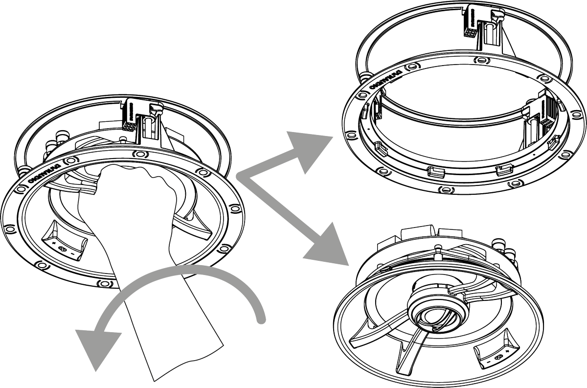
Separate the Speaker Module from its Installation Frame by gripping the tweeter arm and turning entire Speaker Module anti-clockwise with respect to the Installation Frame. Then withdraw the Speaker Module from the Installation Frame.
Having selected the installation position and checked for the presence of studs (joists), pipe work, ducts or cables, mark a cut-line on the ceiling using the supplied template. Check that the diameter of the cut-line is correct: 210 mm (81⁄4 in) for the P4-C65 and P4-DVC65, and 260 mm (101⁄4 in) for the P4-C80.
Use an appropriate tool to cut along the cut-line to create a cut-out in the ceiling. Trial fit the Installation Frame in the cut-out to check clearances.
Note
The orientation of the Installation Frame within the cut-out is inconsequential.
Note
If using a pre-construction ring, follow the instructions in the pre-construction document.
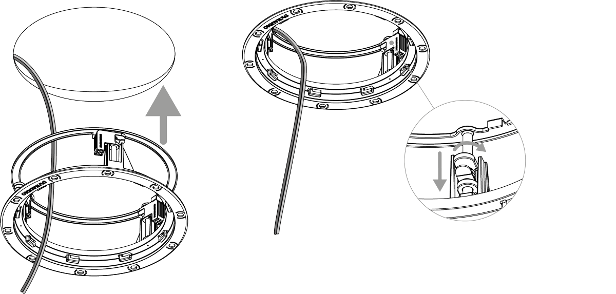
With the ceiling cut-out checked, the Installation Frame can be installed. Lift the frame into place and while holding it against the ceiling with one hand use the other hand to turn the three yellow securing clamps outwards and slide them down against the inner surface of the drywall (plasterboard).
Note
If speaker cables are not already installed it should be done at this stage. It is possible that access will be required through the floor above to route the cables. Use low resistance speaker cable with clear polarity marking on its insulation. Low resistance is especially important if the length of cable from amplifier to speaker exceeds 5 m. Your local Dynaudio retailer or distributor will be able to offer advice on speaker cable selection if required.
Pull the speaker cable through the Installation Frame and ceiling cut-out. The length of free cable should be sufficient to allow the Speaker Module to be held in one hand while connecting the cable to the Speaker Module terminals with the other hand.
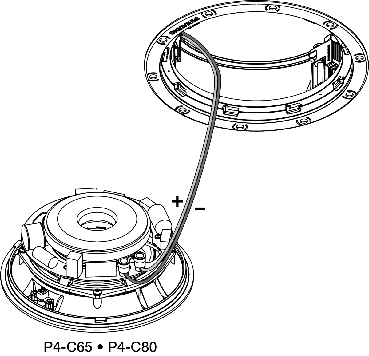
The speaker cable can now be connected to the Speaker Module. Strip 15 mm insulation from the cable (if necessary), twist the wire strands and insert the stripped ends into the appropriate speaker spring terminals.
If the ceiling speaker is a P4-C65 or P4-C80 model simply ensure that the positive conductor is connected to the red speaker terminal and the negative conductor is connected to the black speaker terminal.
P4-C65/C80
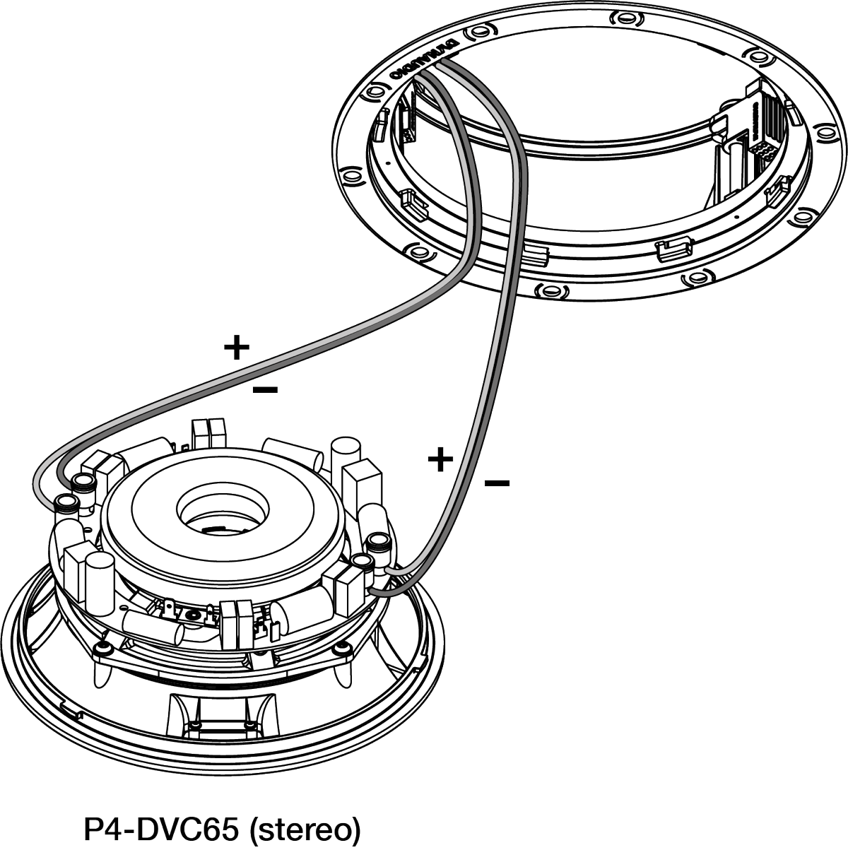
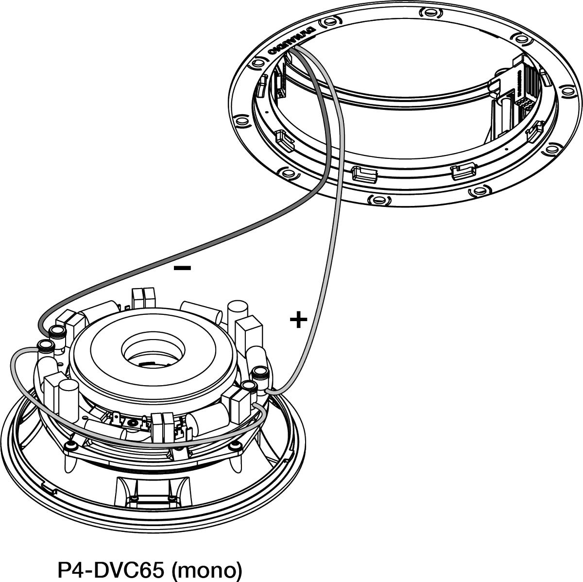
If the speaker is a P4-DVC65 model it can be connected in one of two modes: Stereo and Mono.
Stereo mode
Stereo mode is appropriate if the P4-DVC65 is to be connected to stereo left and right amplifier channels. Connect the positive and negative conductors from each amplifier channel to one set of red and black speaker terminals. Ensure that the positive conductors are connected to red terminals and the negative conductors are connected to black terminals.
Mono mode
Mono mode is appropriate if the P4-DVC65 is to be connected to a single amplifier channel. Connect the positive conductor to the left hand red terminal and the negative conductor to the right hand black terminal. Use a short length of cable to connect the remaining two terminals together.
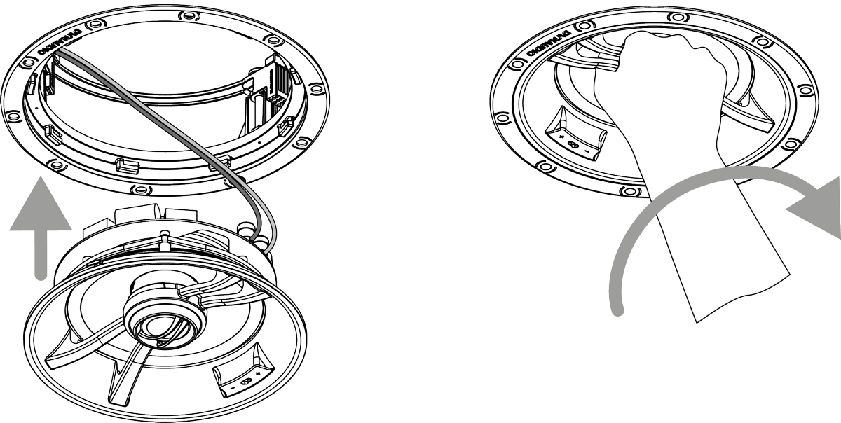
With the speaker cables connected, the Speaker Module can be lifted up into the Installation Frame. Take care that the speaker cable is positioned in such a way that it will not get trapped as the Speaker Module is secured into the Installation Frame and is not touching the Speaker Module in such a manner that it is likely to result in audible vibrations. Once the Speaker Module is fully inserted into the Installation Frame, grip the tweeter arm and turn the entire Speaker Module clockwise to lock it in place. It will click when secure.
Note
To remove the Speaker Unit from the Installation Frame grip the tweeter arm and turn the Speaker Module anti-clockwise.
The high frequency tonal balance of Performance Series speakers can be adjusted to suit different installation environments. A tweeter level switch located on the front bezel offers +3 dB, 0 dB and -3 dB options.
The tweeter module on the P4-C65 and P4-C80 can additionally be tilted to aim towards the listening position if desired.
Note
Different tweeter levels may be appropriate to suit different listening environments. An environment dominated by carpets, soft furnishings and curtains for example might require a higher tweeter level than an environment where tiled floors and glass predominate.
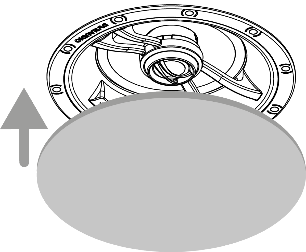
In-ceiling speaker installation is completed by fitting the grille. The grille is secured magnetically and requires no more than placing into position.
Note
Square Performance Series in-ceiling speaker grilles are optionally available. Magnetic attachment enables square grilles to be rotated as required to align perfectly with ceiling or wall lines.
Note
If the ceiling is to be painted following speaker installation, Speaker Units should first be removed from their Installation Frames. Speaker grilles should be painted before being fitted.
In-wall Speaker Installation
Note
These installation instructions broadly assume that speaker cables are pre-installed in ceilings and walls.
To install a Performance Series in-wall speaker, proceed as described in the following paragraphs and accompanying diagrams:
Having selected the installation position and checked for the presence of studs (joists), pipe work, ducts or cables, mark a portrait orientation cut-line on the wall using the supplied template. Check that the dimensions of the cut-line are correct: 175 x 275 mm (67⁄8 x 10⁷⁄8 in) for the P4-W65, 215 x 370 mm (81⁄2 x 141⁄2 in) for the P4-W80 and 175 x 340 mm (67⁄8 x 133⁄8 in) for the P4-LCR50.
Note
The P4-W65 and P4-W80 are intended to be used in portrait orientation with their tweeters uppermost. The P4-LRC50 can be used in either portrait or landscape orientation.
Use an appropriate tool to cut along the cut-line to create a cut-out in the wall. Trial fit the Speaker Unit in the cut-out to check clearances.
Note
If speaker cables are not already installed it should be done at this stage. It is possible that access will be required through the opposite side of the wall to route the cables. Use low resistance speaker cable with clear polarity marking on its insulation. Low resistance is especially important if the length of cable from amplifier to speaker exceeds 5 m. Your local Dynaudio retailer or distributor will be able to offer advice on speaker cable selection if required.
The length of free cable should be sufficient to allow the Speaker Unit to be held in one hand while connecting the cable to the terminals with the other hand.
The speaker cable can now be connected to the Speaker Unit. Strip 15 mm insulation from the cable (if necessary), twist the wire strands and insert the stripped ends into the Speaker Unit spring terminals. Ensure that the positive conductor is connected to the red speaker terminal and the negative conductor is connected to the black speaker terminal.

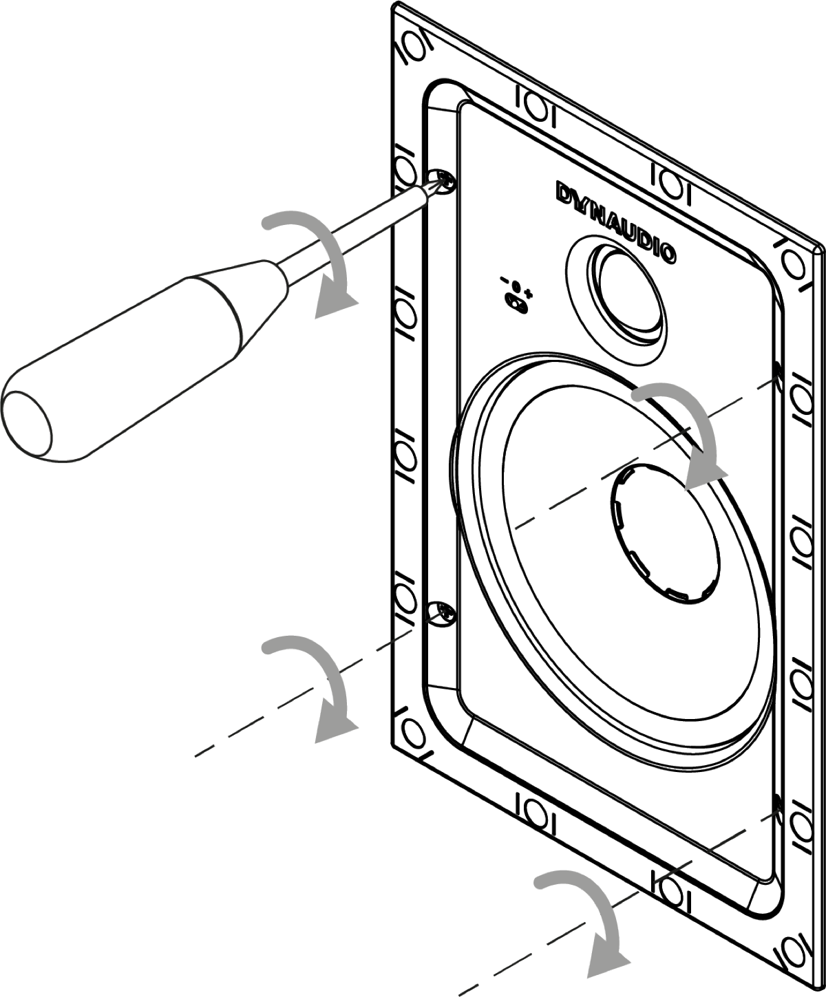
With the cut-out checked, and the cable connected the speaker can be installed. Insert the Speaker Unit into place and while holding it against the wall with one hand use the other hand to turn the four cross-head screws clockwise untill they are tight. Do not over-tighten the screws. Turning the screws first rotates the four internal securing clamps and then moves them inwards to secure the Speaker Unit against the inner surface of the drywall (plasterboard).
The high frequency tonal balance of the Performance Series speakers can be adjusted to suit different installation environments. A tweeter level switch located on the Speaker Unit front bezel offers +3 dB, 0 dB and -3 dB options. The level adjustment operates from approximately 3 kHz upwards.
Note
The +3 dB tweeter level option may be appropriate if, for example, carpets, soft furnishings and curtains dominate in the listening environment. Alternatively the -3 dB option may be more suited to an environment where hard floors and glass predominate. In more balanced acoustic environments, the 0 dB option is likely to be most appropriate.
With the speaker connected and secured into the Installation Frame, in-wall speaker installation is completed by fitting the grille. The grille is secured magnetically and requires no more than placing into position.
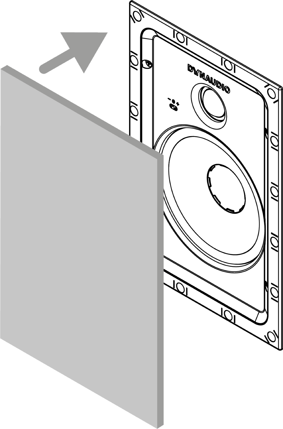
Note
If the wall is to be painted following speaker installation, the speakers must be protected from paint ingress. This can be achieved using paper cut to size and secured with masking tape. Speaker grilles should be painted before being fitted.
Specifications
P4-C65
| Parameter | Value |
|---|---|
| Type | 2-way in-ceiling |
| Drivers – Tweeter | 25 mm (1 in) |
| Drivers – Bass/mid | 165 mm (61⁄2 in) |
| Frequency response | 46 Hz – 20 kHz ±3 dB |
| Impedance – nominal | 8 Ω |
| Impedance – minimum | 5 Ω |
| Sensitivity | 87.5 dB @ 1 m, 2.83 V |
| Rated power* | 40 W |
| Long term power* | 80 W |
| Tweeter level options | -3 dB, 0 dB +3 dB |
| Tweeter orientation | Pivoting 360° |
| Dimensions/Depth | Ø 232 mm / 70 mm Ø 91⁄8 in / 23⁄4 in |
| Cut-out dimensions | Ø 210 mm 81⁄4 in |
P4-DVC65
| Parameter | Value |
|---|---|
| Type | 2-way in-ceiling |
| Drivers – Tweeter | 2 x 25 mm (1 in) |
| Drivers – Bass/mid | 165 mm (61⁄2 in) |
| Frequency response | 46 Hz – 20 kHz ±3 dB |
| Impedance – nominal | 2 x 4 Ω |
| Impedance – minimum | 2 x 3.2 Ω minimum |
| Sensitivity | 87.5 dB @ 1 m, 2.83 V |
| Rated power* | 2 x 20 W |
| Long term power* | 2 x 40 W |
| Tweeter level options | 0 dB, -3 dB |
| Tweeter orientation | Fixed |
| Dimensions/Depth | Ø 232 mm / 70 mm Ø 91⁄8 in / 23⁄4 in |
| Cut-out dimensions | Ø 210 mm 81⁄4 in |
P4-C80
| Parameter | Value |
|---|---|
| Type | 2-way in-ceiling |
| Drivers – Tweeter | 25 mm (1 in) |
| Drivers – Bass/mid | 200 mm (8.0 in) |
| Frequency response | 48 Hz – 20 kHz ±3 dB |
| Impedance – nominal | 8 Ω |
| Impedance – minimum | 5 Ω |
| Sensitivity | 89.0 dB @ 1 m, 2.83 V |
| Rated power* | 50 W |
| Long term power* | 100 W |
| Tweeter level options | -3 dB, 0 dB +3 dB |
| Tweeter orientation | Pivoting 360° |
| Dimensions/Depth | Ø 280 mm / 87 mm Ø 11 in / 31⁄2 in |
| Cut-out dimensions | Ø 260 mm 101⁄4 in |
P4-W65
| Parameter | Value |
|---|---|
| Type | 2-way in-wall |
| Drivers – Tweeter | 25 mm (1 in) |
| Drivers – Bass/mid | 165 mm (61⁄2 in) |
| Frequency response | 46 Hz – 20 kHz ±3 dB |
| Impedance – nominal | 8 Ω |
| Impedance – minimum | 5 Ω |
| Sensitivity | 87.5 dB @ 1 m, 2.83 V |
| Rated power* | 40 W |
| Long term power* | 80 W |
| Tweeter level options | -3 dB, 0 dB +3 dB |
| Dimensions/Depth | 198 x 296 mm / 63 mm 73⁄4 x 1111⁄16 in / 21⁄2 in |
| Cut-out dimensions | 175 x 275 mm 67⁄8 x 10¹³⁄16 in |
P4-W80
| Parameter | Value |
|---|---|
| Type | 2-way in-wall |
| Drivers – Tweeter | 25 mm (1 in) |
| Drivers – Bass/mid | 200 mm (8.0 in) |
| Frequency response | 46 Hz – 20 kHz ±3 dB |
| Impedance – nominal | 8 Ω |
| Impedance – minimum | 5 Ω |
| Sensitivity | 89.0 dB @ 1 m, 2.83 V |
| Rated power* | 50 W |
| Long term power* | 100 W |
| Tweeter level options | -3 dB, 0 dB +3 dB |
| Dimensions/Depth | 237 x 392 mm / 77 mm 95⁄16 x 153⁄8 in / 3 in |
| Cut-out dimensions | 215 x 370 mm 81⁄2 x 149⁄16 in |
P4-LCR50
| Parameter | Value |
|---|---|
| Type | 2-way in-wall |
| Drivers – Tweeter | 25 mm (1 in) |
| Drivers – Bass/mid | 2 x 130 mm (5.0 in) |
| Frequency response | 48 Hz – 20 kHz ±3 dB |
| Impedance – nominal | 4 Ω |
| Impedance – minimum | 3.2 Ω |
| Sensitivity | 89.0 dB @ 1 m, 2.83 V |
| Rated power* | 50 W |
| Long term power* | 100 W |
| Tweeter level options | -3 dB, 0 dB +3 dB |
| Dimensions/Depth | 360 x 195 mm / 77 mm 141⁄4 x 73⁄4 in / 3 in |
| Cut-out dimensions | 175 x 340 mm 67⁄8 x 133⁄8 in |