LYD
Introduction
Welcome and congratulations on your purchase of Dynaudio Personal Reference Monitors. Each loudspeaker is constructed by Dynaudio in Denmark to meet very high standards. The speakers are only one part of your monitoring system. Speakers work together with how they are placed in the room to create a playback system that delivers accurate sound reproduction.
In this manual you will find information on how best to position both the speakers and listener to get the best performance from your Dynaudio loudspeakers. When your speakers are properly setup and the rear panel settings are optimized, your mixes will translate better to other playback systems including home theaters, car stereos, and headphones.

Things You Will Need
- Tape Measure
- White String
- Marker
Optional
- Dynaudio Meter app for iOS devices
Dynaudio Meter App
Dynaudio has created an iOS app that contains a source of pink noise, SPL meter, and RTA spectrum analyzer. This app is designed to assist you in positioning and calibrating your speaker system in the listening room.
Other Resources
Please also visit our web site
You will find additional information including:
- Questions and answers about Dynaudio products and technical information
- Dynaudio events and news
Important safety information

The lightning flash with an arrowhead symbol within an equilateral triangle, is intended to alert the user to the presence of uninsulated “dangerous voltage” within the product’s enclosure that may be of sufficient magnitude to constitute a risk of electric shock to persons.

The exclamation point within an equilateral triangle is intended to alert the user to the presence of important operating and maintenance (servicing) instructions in the literature accompanying the product.
- Read these instructions.
- Keep these instructions.
- Heed all warnings.
- Follow all instructions.
- Do not use this apparatus near water.
- Clean only with dry cloth.
- Install in accordance with the manufacturer’s instructions.
- Do not install near any heat sources such as radiators, heat registers, stoves, or other apparatus (including amplifiers) that produce heat.
- Do not defeat the safety purpose of the polarized or grounding-type plug. A polarized plug has two blades with one wider than the other. A grounding type plug has two blades and a third grounding prong. The wide blade or the third prong are provided for your safety. If the provided plug does not fit into your outlet, consult an electrician for replacement of the obsolete outlet.
- Protect the power cord from being walked on or pinched particularly at plugs, convenience receptacles, and the point where they exit from the apparatus.
- Only use attachments/accessories specified by the manufacturer.
 Use only with the cart, stand, tri-pod, bracket, or table specified by the manufacturer. When a cart is used, use caution when moving the cart/apparatus combination to avoid injury from tip- over.
- Unplug this apparatus during lightning storms or when unused for long periods of time.
- Refer all servicing to qualified service personnel. Servicing is required when the apparatus has been damaged in any way, such as powersupply cord or plug is damaged, liquid has been spilled or objects have fallen into the apparatus, the apparatus has been exposed to rain or moisture, does not operate normally, or has been dropped.
Warning!
To reduce the risk of fire or electrical shock, do not expose this equipment to dripping or splashing and ensure that no objects filled with liquids, such as vases, are placed on the equipment
This apparatus must be earthed.
Use a three wire grounding type line cord like the one supplied with the product.
Be advised that different operating voltages require the use of different types of line cord and attachment plugs.
Always observe the local safety regulations. Ensure that the factory-set power requirements for the device (refer to the label on the back of the monitor) corresponds to the mains supply in your region.
This equipment should be installed near the socket outlet and disconnection of the device should be easily accessible.
To completely disconnect from AC mains, disconnect the power supply cord from the AC receptacle.
The mains plug of the power supply shall remain readily operable.
Do not install in a confined space.
Do not open the unit – risk of electric shock inside.
Caution:
You are cautioned that any change or modifications not expressly approved in this manual could void your authority to operate this equipment
Service:
There are no user-serviceable parts inside.
All service must be performed by qualified personnel.
Disposal
Disposal of used electrical and electronic equipment (applicable in European countries with separate collection systems for this equipment)

This symbol on the product or its packaging indicates that the product may not be treated as household waste. Instead it must be handed over to the applicable collection point for the recycling of electrical and electronic equipment. By ensuring this product is disposed of correctly, you will help prevent potential negative consequences for the environment and human health. The recycling of materials helps to conserve natural resources. For more detailed information on recycling this product, please contact your local authority, community waste disposal of, or the shop where you purchased the product.
EMC/EMI
This equipment has been tested and found to comply with the limits for a Class B Digital device, pursuant to part 15 of the FCC rules.
These limits are designed to provide reasonable protection against harmful interference in residential installations. This equipment generates, uses and can radiate radio frequency energy and, if not in- stalled and used in accordance with the instructions, may cause harmful interference to radio communications. However, there is no guarantee that interference will not occur in a particular installation. If the equipment does cause harmful interference to radio or television reception, which can be determined by turning the equipment off an on, the user is encouraged to try to correct the interference by one or more of the following measures.
Reorient or relocate the receiving antenna.
Increase the separation between the equipment and receiver.
Connect the equipment into an outlet on a circuit different from that to which the receiver is connected.
Consult the dealer or an experienced radio/TV technician for help.
For Customers in Canada:
This Class B digital apparatus complies with Canadian ICES-003.
Cet appareil numérique de la classe B est conforme à la norme NMB-003 du Canada.
Product Overview
The transducers of your Dynaudio LYD speaker will achieve better sound quality after breaking in. Especially after the first hours of use, you may notice a significant advance in sound quality, and further subtle improvements in subsequent hours of use.
Amplifier
The LYD speaker range features an integrated Class-D amplifier with analog inputs. All connections and settings are available on the backplate of the amplifier. Please do not remove the amplifier yourself.
If servicing is required, please contact your Dynaudio dealer.
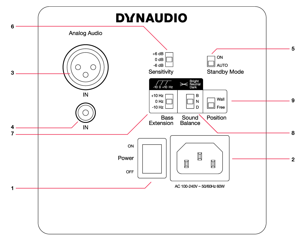
- Power ON/OFF switch
- AC power Input (100-230V)
- Balanced analog input (XLR)
- Unbalanced analog input (RCA)
- Standby Mode switch – Turns auto-standby ON/OFF
- Sensitivity switch – Changes max. input voltage
- Bass Extension switch – Changes cut-off frequency of the speaker
- Sound Balance switch – Switches between three tilt filter settings
- Position switch – Turns boundary effect filters ON/OFF
Positioning the speakers
In order to get the best performance from your Dynaudio speakers, care must be taken in positioning them in the listening environment. The room greatly affects the sound so the position and angle of the speakers relative to the walls, ceiling and floor is critical in any listening environment.
Acoustic Axis
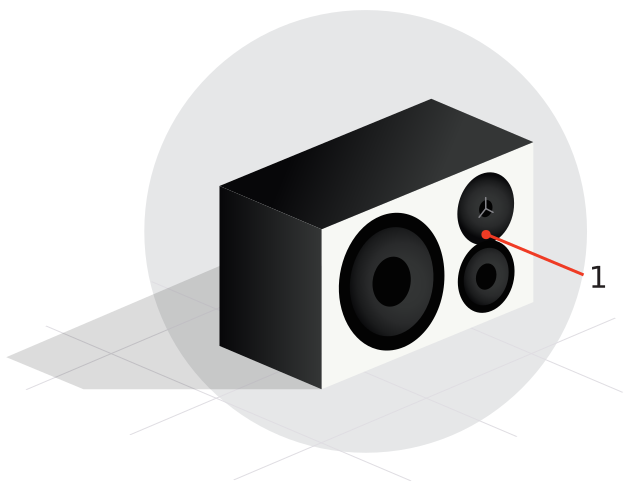
The acoustic axis is an imaginary line passing through the center point on the speaker and is used for positioning. This point, shown in Figure 3, should be used for measuring the distance and angle to the listener. The point is positioned half the distance between the boundary of the tweeter and the boundary of the woofer or midrange driver. LYD 5, 7 & 8 are designed to be positioned vertically and pointed directly at the listener, while the LYD 48 is designed to be used horizontally.

Room Boundaries
Each surface in the room constitutes a boundary for sound; floor, walls, and ceiling. Room boundaries will reflect sound to one degree or another depending on what their surface is made of; hardwood, drywall, carpet etc. Placing speakers very close to any boundary should be avoided. The closer a speaker is to a room boundary, the more anomalies there can be in the low frequency response of the system. Placing a speaker close to more than one boundary (e.g. in a corner) creates even worse problems in many cases.
Conversely, placing speakers exactly halfway between room boundaries can over-excite fundamental standing waves in the room, making the bass response less reliable. This also holds true for the listening position. These room anomalies are always present and good placement of the speaker and listener will reduce their effect.
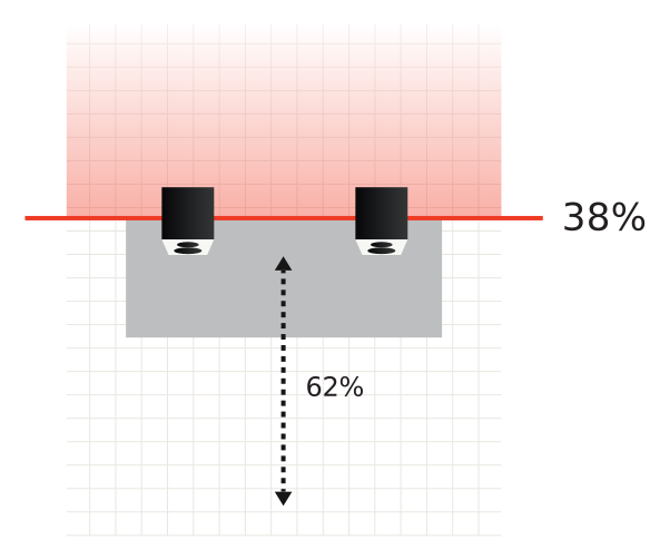
A good rule of thumb is to place speakers somewhere between one quarter and one third of the distance between room boundaries as shown in Figure 4. Also, make sure the listening position is not right in the center of the room if possible. In larger rooms, this is less critical than in small rooms.
Sometimes this ideal positioning is not possible. Limitations in space and other equipment or furniture in the room will dictate some aspects of the speaker position. The idea is to do the best you can with the limitations you have.
Listening Distance
The LYD 5,7 & 8 speakers are designed as near field monitors. Near field monitors should be placed relatively close to the listener, between 1 and 2 meters. LYD 48 can be used both as a near or mid field monitor. The ideal listening distance is between 1.5 and 2.5 meters.
Speakers on the Desk
These loudspeakers are designed to work well in a variety of positions, even very close, placed on the work surface in front of you. If they are resting on a desk or console, they may be tilted up to aim at ear level with great results.
Speaker Stands
If you need to place your speakers on stands behind your work surface or computer screens at a greater distance, it is recommended that you use a subwoofer to augment the low frequency response. This will help the speaker system achieve a reasonable volume without overdriving the speakers.
Listening Angle
To begin with, the speakers should be placed so that the drivers are oriented vertically, with the tweeter directly above the woofer. This orientation ensures correct time alignment between the high and low frequencies as they arrive at the listener.
Horizontal Angle
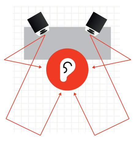
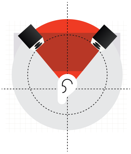
The speakers should be placed so that they create a 60 degree angle between the speakers, as shown in Figure 5. The easiest way to accomplish this without measuring the angle, is to create an equilateral triangle between the speakers and the listener. In other words, the distance between each speaker should equal the distance from each speaker to the listener. The LYD 48 can be positioned with the woofers inside (recommended) or outside, depending on how the equilateral triangle can be achieved best. Make sure to take measurements from the acoustic axis of the speaker.
An easy method to do this involves the tape measure and string.
- With the tape measure, check to see that the speakers are not placed further away than 2 meters for the best response.
- Once you have initially placed the speakers, take the string holding one end at the speaker’s acoustic axis and stretch it out to the listening position.
- Mark this point with a marker.
- Do this again for the other speaker to ensure that they are both the exact same distance from the listener.
- Use the string to measure the distance between each speaker. This should also be the same, forming and equilateral triangle between the two speakers and the listener.
- Make adjustments as necessary to place the listener and speakers at the same distance from each other
Vertical Angle
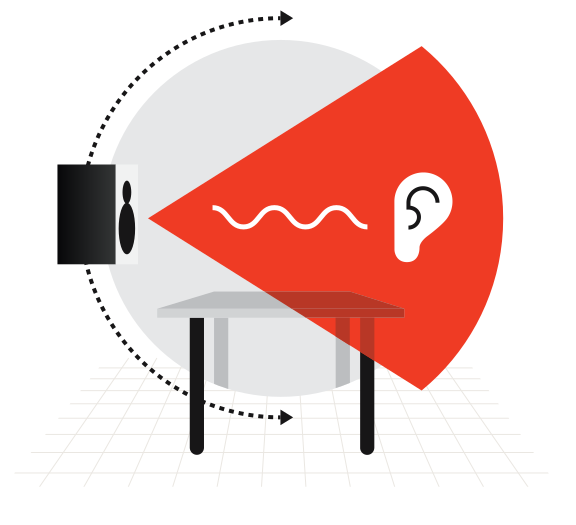
The vertical angle of the speakers should orient the loudspeaker directly toward the listener’s ear level. If the speaker is placed higher than the listener, they should be angled downward. Conversely, if the speaker is below the listener’s ear level, they can be angled upward to point at the ear as shown in Figure 6.
Connecting the Speakers
Mains
Ensure that you have the correct mains cable for your region. The power supplies in the loudspeaker have switching inputs that automatically detect the incoming voltage and will adjust to either 120V or 220V, depending on your location.
Plug in the provided AC cable to the loudspeaker and then to the outlet. Turn the speaker on to ensure that they power up correctly by looking to see that the power LED is lit on the back panel. Once this is confirmed, turn the speakers off before connecting audio signals.
Standby Mode
The loudspeakers have a standby mode that helps conserve energy when they are not in use.
On – When set to ON, the speakers remain powered on until the mains switch is turned off.
Auto – When set to AUTO, the speakers will automatically enter a power-saving mode when not in use that shuts down the amplifier section until audio is detected at the input.
Audio Signals
There are two physical inputs you can choose:
- RCA-type unbalanced
- XLR balanced or unbalanced
The balanced XLR connection is preferable as it can reduce noise and hum from the surroundings but both connections can provide a high quality input signal. Connect the outputs of your mixer, audio interface or monitor controller to the loudspeaker inputs.
Caution
Before sending audio to the loudspeakers, set the sensitivity to -6dB and adjust the outputs of your mixer or audio interface to a low setting and gradually turn up the signal until you get a reasonable volume. This will prevent any accidental overload of the loudspeakers.
Adjusting the Volume
There is a three-position switch that adjusts the input sensitivity for the loudspeaker.
Depending on the output level of your audio mixer, interface, or monitor control system, you can choose a setting that optimizes the gain staging into the loudspeaker.
- +6dB = 0dBu /.775V max
- 0dB = +6dBu /1.5V max
- -6dB = +12dBu /3.1V max
If you are using a professional interface with a max output of +20dBu or more, then a setting of -6dB on the loudspeaker is the most appropriate. If you are using equipment that runs at a consumer or domestic output level (-10dBV nominal), then the +6dB setting is better.
DSP Settings
Dynaudio engineers have painstakingly created a DSP controller for these speakers that lets you tailor the sound to your particular environment. The DSP settings provide precision adjustments that optimize the speakers for the listening space.
Bass Extension
Low frequencies take an exponentially larger amount of energy to reproduce than high frequencies. That is why the bass extension setting affects how loud the speaker will respond.
At its lowest setting (-10 Hz), the low frequency range is extended by 10Hz. This will also reduce the maximum volume that the speaker can achieve. The default setting of 0 Hz limits the range of low bass while increasing the maximum volume of the loudspeaker. The +10 Hz setting has the least amount of bass extension but the loudest volume possible from the loudspeaker.
- -10 Hz (greatest low frequency extension, - 5 dB output)
- 0 Hz
- +10 Hz (loudest output with least low frequency extension, +5 dB output)
As most professional mixers tend to mix at relatively low volumes (~70-85 dB SPL), the greatest amount of bass extension (-10 Hz) can be used. As you increase the playback volume, you may need to reduce the amount of bass extension in order to prevent overdriving the loudspeaker.
Sound Balance
The sound balance, or tilt filter, represents a refined way to affect the overall tone of the speaker. Depending on the room treatment among other factors, it may be necessary to make the loudspeaker darker or brighter than the normal setting. A dead sounding room with a great deal of treatment might need a brighter setting than a live room with many reflective surfaces.
Sound Balance has three settings:
- Bright (20 Hz -1,5dB, 20kHz +1,5dB)
- Neutral
- Dark (20 Hz +1,5dB, 20 kHz -1,5 dB)
What this filter actually does is tilt the entire spectrum by 1,5 dB at either end using minimal phase or linear phase filters to either brighten or darken the overall response. This minimal filter alters the tonality without inducing audible phase anomalies, thereby maximizing the linearity of the loudspeaker.
Position
If you have positioned your speakers within 50cm of a back wall boundary, the position switch should be placed in the “Wall” setting. This will help with anomalies created by reflections coming off the back wall, especially in the lower frequencies. If your speakers are placed further than 50cm from any wall surface, use the “Free” setting.
Listening Tests
Once you have your speakers properly positioned, its time to start listening to them. Subjective listening tests can be made with reference material that you are familiar with; a favorite album, movie or other recording. Objective tests can be made simply with a smartphone app or more sophisticated acoustic measurement system.
Reference Material
Play some recorded material that you are familiar with through the speakers to see if the sound is what you expect. Adjust the tilt filters both directions to hear the different tonalities that are possible. It is also suggested that you listen to material you know actually sounds bad or has defects in the recordings. A truly neutral loudspeaker will reveal these defects clearly.
The whole point to a good loudspeaker is to get accurate representation of the sound, good or bad, so that mix decisions can effectively be made. Adjust the tilt filter to the setting you are most comfortable with.
Pink Noise
For an objective test of the speaker’s response, you will need a metering system. This consists of a device that can measure the spectral output of the loudspeaker in real time and a source of pink noise that can be played back through the loudspeakers.
- RTA Spectral Analyzer
- Pink Noise Source
Dynaudio has created an iOS app with these tools built in so you can quickly test and calibrate your LYD speakers using your iPhone, iPad or iPod touch. In the Apple App Store, search for “Dynaudio Meter” to locate and download this free app.
You can connect the device directly to the speakers using a conventional headphone to RCA adapter. Play the pink noise from the Dynaudio Meter and adjust the level for a reasonable playback volume. If you wish to play pink noise from your computer workstation, a WAV file containing pink noise is available at:
Play the pink noise through one speaker at a time at a reasonable level (~80-85dBA) and place the iPhone or iPad at the listening position. Change the Sound Balance filter to see how the response changes the response curve in the RTA. Pink noise is a balanced level of noise across the entire spectrum. In the RTA display, the reading should be as level and even as possible.
If you notice excessive levels in the low frequencies, try setting the Sound Balance filter to Bright (B) and check the results. If the spectrum analyzer shows a greater degree of high frequencies, set the tilt filter to dark (D) and check the results.
Once you have the tilt filter set for the flattest response curve in the RTA, return to your reference material to see how it sounds. Through this process of objective tests with the RTA and subjective listening tests with you ears, you will arrive at the best setting for your Dynaudio loudspeakers.
Final Tweaks
Beyond the settings for the loudspeakers, additional tweaks may be desired to improve the response of the system and room environment. You may discover that a reflective surface is causing a high frequency anomaly or perhaps room modes are disturbing the bass response in the room.
First Reflection Treatment
Sound reflecting off of hard surfaces that are close to the listening position can cause problems in the high frequency response and imaging of the loudspeakers. These first reflections can be relatively easy to fix in many cases. Figure 7 shows some common causes of first reflections in a typical control room.
First reflections can be located easily by using a mirror placed on various surfaces in the studio to check if you can see either loudspeaker in the mirror when sitting in the listening position. If you can see either loudspeaker in the mirror, it follows that upper frequencies will bounce off that surface directly back to the listening position and potentially cause response problems.
Placing absorptive material on these surfaces will reduce the effect of first reflections and improve the sound of the system. The thicker the acoustic material is, the more effective it will be. Also, creating an air space behind the material will improve its effectiveness. Place as much absorption that is practical at the first reflection points to improve the response of the system.
Bass Trapping
If you notice any peaks or dips in the low frequency response curve of the RTA (20-250 Hz), they may be caused by room modes. Room modes occur at specific low frequencies that have wavelengths that are equal to or multiples of the dimensions of the listening room.
For example, if the listening room is 4 meters long, there may be a room mode at 43 Hz since its wavelength is about 8 meters. What this means is that for this frequency, the room response will change dramatically depending on the position of the listener and the loudspeaker. You may hear a more of this frequency or less of it depending on the listening position in the room. Modes can be formed from all dimensions of the room; length, width, and height. The solution is to place sound absorption designed for low frequencies in the most effective places to reduce the effect of room modes.
Many manufacturers make sound absorptive devices called bass traps that are designed to be placed in or near corners and will reduce the amount of reflected low frequency energy in the room. By dampening the resonance of the modes, the low frequency response of the room may be smoothed out.
When placing bass traps, always check the resulting frequency response curve with pink noise and an RTA to ensure that the loudspeaker response is improving. Then listen to your favorite reference material to see how this affects it.